In the last two days started fixing bugs. Put back on working state the 2D, 3D shapes tools, Cut and Extrude. Fixed bugs related to duplicate shape drawing and shape intersection on these tools.
Modified the Rectangle tool to draw rectangles instead of parallelograms, not enabled yet the latest implementation as it has some functionality conflicts with the constraints code. Will finalize it tomorrow.
Remained to put back in working state the translate, offset, mirror tools, some fixes at spline.
Wednesday, March 31, 2010
Tuesday, March 30, 2010
Vertical Line and Horizontal Line Constraints
As a part of the improving the Solver component, the horizontal line and vertical line should make a more precise draw. Because of this the solver was extended to support this new two shapes. There are also a lot of fixes and crashes.
The constraints of vertical and horizontal lines are two way: meaning that the horizontal/vertical lines themselves can be constrained by other shape like middle of edge. In this way hopefully the draw will be more precise.
Trying to draw the custom shape that was put as a sketch I found a selection bug that makes that if you draw a circle on top of rectangle and no face-split occurs, it will make that the first selected shape will be the rectangle, not the circle, which most probable is not the desirable effect (you will likely want to select the latest shape, not the first defined one).
As of today I will fix more bugs that appeared in this rewrite/refactor but as of today is a close to complete code.
The supported constraints:
- start of edge (meaning a point from shape's dependencies)
- middle of edge
- vertical/horizontal line that is integrated with the solver
- middle of rectangle/rectangle 2p
Monday, March 29, 2010
Squashing Bugs in Solver
There were some bugs in solver as most of constraints that were added can create crashes (like the middle of edge creates internally a wire check that makes that things to work nice for a line, but not that nice for a rectangles). On the same manner there was fixed the crash when setting up an axis coordinate based on a point coordinate given the fact that an axis and a point3D are different shapes even they can work on the same initial location.
Middle of face (for rectangle and rectangle2p) was also seem to work right now.
A design limitation I want to get it right is to apply more constraints on the same node that a small fix was done, but the code was not yet commited as need more testing. Also horizontal line and vertical line are just one way integrated, meaning that those lines are registered in solver and they can follow points from lines (in general) but they are not constraining none of the generated geometry (yet).
Sunday, March 28, 2010
Middle Edge Solver Constraint, Fallback Code
Middle of edge is eventually here. Also the code closes to get shape to the final code. There are fixes on crashes (sometimes you will get recursive call on stack and crashes, hope to target this bug). Also I found a limitation on design that I will try to fix it as I wanted to align to horizontal line/vertical line and this cannot be done both in case if you want to put a point just on the both intersections (probably an extra solver type should be added, like there is a SolverPoint).
This new Solver functionality enable adding constraints that make sense (like end of a line, middle of an edge, I will add very soon: middle of rectangle, middle of rectangle2p - the 2D rectangle) but in a lot of other cases, those constraints are not that important: for instance in case of spline's points, or in cases that the code gets complex on adding a constraint that rarely is needed (middle of base of the pyramid!?). For those cases the old solver code was added nicely in the current design as a fallback code.
This new Solver functionality enable adding constraints that make sense (like end of a line, middle of an edge, I will add very soon: middle of rectangle, middle of rectangle2p - the 2D rectangle) but in a lot of other cases, those constraints are not that important: for instance in case of spline's points, or in cases that the code gets complex on adding a constraint that rarely is needed (middle of base of the pyramid!?). For those cases the old solver code was added nicely in the current design as a fallback code.
Friday, March 26, 2010
Solver Code Review
I worked to make the mid-edge constraint available which will depend of the SubShape code and I had some small problems but I will fix them tomorrow. Easier to be done will be middle of rectangle that I will also do it today. There are still some remaining missing functionality and I hope that everything will be done over this weekend.
There is also an UI concept that will expose the solver sensitivity in status-bar for easier setup using a slider. This work is done by our contributor Cristian. We don't know if this is the best way, but at least we explore this area.
There is also an UI concept that will expose the solver sensitivity in status-bar for easier setup using a slider. This work is done by our contributor Cristian. We don't know if this is the best way, but at least we explore this area.
Tuesday, March 23, 2010
Point to Point Constrains Setup from Solver
 The solver component do automatically make possible to link lines with their points and dragging first line will drag all linked edges. This is an important design milestone because this rethinking makes the solver component to reach more information which is used for providing more useful hints. Also there is much fewer intervention from the developer standpoint (meaning the old pattern: add shape, solver.generateInterestingGeometry(..), solver.AddGeometry(intersting geometry);
  was removed as is not needed.
Solver's interesting geometry is based right now by it's function name and also is solved by a factory.
I will work to add more constraints (middle of edge for example, end of edge), add it for more shapes (the canonical ones, also for helper geometry like: horizontal line, vertical line). And at last, but not at least: to find and fix crashes and bugs that appear on this features.
Improvements on Solver's Logic
Solver code was previously an external component from both model code (document) and also from the view code. The solver also creates points that have no meaning that coordinate. Work was done to clean the duplicate code and to make constructions only once.
The design was extended and work (only on line for now) to add extra information in solver points (like: EndPoint and the point index). Today I will work that this extra points to be integrated in MetaActions so clicking on an end point will add automatically a constraint so moving a line by editing them will make that lines to propagate the constrained changes forward.
If I will finish this faster and no bugs I will create more constraints that apply for rectangles (as for now the solver will use a factory to build that custom constraints based on shape type). At the end I hope to create much faster the sketch by improving the sketch.
Monday, March 22, 2010
Finalized offset
Made the offset tool final code. It can be applied on Faces, the result is another Face type shape.
Couldn't find a trick when generating bigger shapes with offset to make the join type to be other than circle, or at least to be a circle with radius 0. The offseting seems to work well only when starting from the biggest shape to the smallest one.
Will move to finish other tasks and keep this one in stand by thinking on how this tool might be improved further.
Friday, March 19, 2010
Offset integrated to command line
Finished porting the offset to meta tools to integrate it with command line. Currently the offset is enabled to work only on 2D closed shapes.
Line offset will be made using copy-paste-translate, translate is also integrated with command line for higher translation precision.
Will improve the offset tool to generate Faces and also make automatic intersections with other faces. When offsetting a shape to generate a bigger shape the open cascade available algorithm rounds the corners, will look also into this issue.

Wednesday, March 17, 2010
Offset merging
Ported a first version of Offset to meta tools so that it integrates with command line.
Not finished porting because encountered some issues at the existing offset tools.
Currently Naro has an Offset 2D tool used to offset wires (a connection of more than one segment, it doesn't work for a simple line) the result is a shape drawn around the original wire and a 3D offset tool using the 3D offsetting algorithm from OpenCascade for solids that gives some strange results.
The plan before finishing the port to command line is to merge all offsetting tools under one tool that detects the particular case and applies the appropriate offset algorithm. The functionality will be slightly changed as follows:
- if offset is applied for one line it will duplicate the line at the offset distance that will be useful for building helper drawing lines - the mouse location will be used to detect the offsetting direction,
- if the offset is applied on a wire built from more than one segment the offset will duplicate the wire at the offset distance - not sure that this will be implemented,
- if offset will be applied on a face like for example a rectangle, an offset algorithm will be applied and the result will be a smaller/bigger rectangle not a translated rectangle like in the case of a line,
- if offset will be applied on a solid will see if some good and quick results can be obtained with the OpenCascade algorithm. Will analyze here if offset on solids is used in industry and remove the functionality if it is not useful.
Will think for a consistent solution for all these situations (for lines the result is a translation for faces and solids it is an offset shape).
Applying Offset on a wire made from more than one line, lines selected with shift+click, generates another problem: it is quite difficult to know when the users finished selecting and started offsetting.
Tuesday, March 16, 2010
Solver Frozen for Some Days
I will be away for some days for family.
Yesterday I've reviewed the Solver's code (as was named, the solver for now is the guidelines component instead a full solver component) as some changes are needed to make it more intelligent. The biggest change from Solver side is that it will be integrated with Command Line (and meta-actions). To make this possible I was need to make it Document-aware to know which shapes are in scene. The previous design was that shapes register to solver the current "magic" points.
The newer design I work on will be the following: the solver will know the scene the user is working on. When a change occur in scene the solver will evaluate the shape and will extract automatically the useful geometry. Making solver aware of what is in scene will make possible to attach (the straight forward) constraints based on the click place that are logical. For example when you create a circle in the center of a rectangle, you will mostly like to remain there. And when you will resize the rectangle, the circle to still remain attached to the same very center.
Yesterday I've changed a lot of code that propagates the SolverPoint/gp_Pnt to NaroCAD codebase as SolverPoint was a duplicate code that there. Also writing skeleton code how the solver will scan the scene to create automatically the magic geometry.
The next changes in this area will mostly appear around Saturday.
Monday, March 15, 2010
Translate integrated with command line
Ported the Translate tool to meta actions. Now it is fully integrated with the command line, translations can be made with higher precision. Added also a drawing animation that displays the translation length while translating.
Will look also at the Offset tool to integrate it with command line and improve it for drawing helper lines.

Will look also at the Offset tool to integrate it with command line and improve it for drawing helper lines.


New Iteration started
Started a new development iteration of 3 weeks that will end with a release. Among the directions planned are:
- improve the command line to get text even is the control is not focused - speeds up the drawing,
- add constraints: center of a face, distance from edge,
- port the translate tool to command line to improve its precision and also fix its bugs,
- improve offset tool to allow quick line offseting to build helper geometry,
- possibility to hide shapes,
- implement ortho,
- layer/tag support,
- add on bottom of window solver buttons to quickly enable/disable certain magic point types,
- improve rectangle tool drawing,
- fix more bugs.
Sunday, March 14, 2010
2D Shapes Created
I created the three helper shapes that work only on XOY plane (for easier setup) and they are accessible both from Lua and from Command Line interface as follows:
horizontal_line(y)
vertical_line(x)
rectangle2p(x1, y1, x2, y2)
But they still are not integrated with solver (this is what I'm going to).
horizontal_line(y)
vertical_line(x)
rectangle2p(x1, y1, x2, y2)
But they still are not integrated with solver (this is what I'm going to).
Saturday, March 13, 2010
Improving Constraints and Relation with Shape Creation
I work for improving the usability of drawing.
My plan for now is this:
- add guideline shapes: vertical and horizontal (infinite) lines that the solver is aware of them so it will make them sticky and make more precise
- add rectangle shape for default planes (XOY, YOZ, XOZ) defined by two points. This combined with guideline lines will make hopefully a breeze to define a (more) precise rectangle from user interface.
- make possibility constraints to be interpreter based instead of function based (most code is here). This will mean that will be possible that when you click a point that is an end of an edge, to get questioned: do you want this point to be linked? and from that moment on the point will be "sticky" with the point you defined on. This can be done with actual design also but need a lot of changes from the shape creation standpoint. As the actual constraints are viewed as "external shapes" and meta-actions work just with one current shape, this will make that you cannot add constraints in the same time when you draw a line. Setting them as an interpreter, will make that possible
- I know how to create a constraint of: "middle of rectangle" or in general: "middle of a face" but yet I don't know how to create a constraint: distance from an edge (because the plane can be arbitrary, when in case of middle of a "faced shape", it's face is the plane you work on) I will need to investigate on. But I want based on the previous work to make the following constraints: - end of edge, middle of edge, middle of rectangle, middle of circle.
- improve solver to: align on main planes on rounding values (like grid values), to align to helper geometry, to ask user for constraint matching and to provide this constraint to that point
This work will hopefully take around two-three days and more on spotting bugs that may occur.
Friday, March 12, 2010
NaroCAD 1.4.1 Released

NaroCAD went a long way from 1.0 when transformations do not exist, was a Windows.Forms application. As of today we are happy to announce the 1.4.1 release which brings to you internal changes to show to you a contextual right click menu, improvements on how is handled the opencascade view in it's WPF context, automatical updates. This also come with more bug-fixes all over the place.
We will continue improving the way things work in the close future so you may
So we may hope you will like this release and you can download it from here.
Cut improvements
Worked at improving Cut algorithm. It works much better, can be applied on the same shape many times without failing. It still has problems if the Cut goes through wires like lines, will have to try to add some wire detection/removal/healing algorithm to cleanup the solid structure.
Also Delete and Box tools were fixed.
Succeeded to draw a simple real model. The drawing process was quite cumbersome. With tasks scheduled for next iterations will boost the usability of the tools, in 2-3 weeks the tools should look much better.
The original shape:

Drawn with Naro:

Cut many times through an extrude:

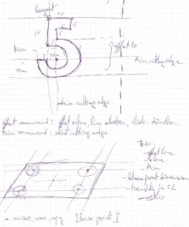
Drawing
Yesterday participated as observer at an AutoCad technical drawing course. I knew how to use AutoCad tools but wanted to see the drawing techniques. It was very interesting to notice the differences and similarities between drawing styles of the engineers. The main idea was they were all drawing some helper lines and establishing base points for their drawings.
Identified the most important functionality that boosts productivity, most of these are already scheduled in next iterations:
- the Ortho and Polar tools that are blocking the angles at which the users can draw seem the most important,
- possibility to offset a line at a specified distance - we could implement this by enabling our Translate tool to be called also from command line. Functionality that will be used to to make the helper lines,
- layers and functionality attached to them are very useful and practical for more complicated projects,
- tool to draw dimensions between two points - possible to use also as a measurement tool,
- add infinite lines,
- the trim and extend tools seem very useful. Will study how these apply in the 3D modeling world,
- mirror, move, copy relative to a base point - mainly we have this functionality - we just need some refinements.

Thursday, March 11, 2010
Fixes on Installer and Reference Loading
Installing a new update may be annoying for a lot of reasons. Some of them are the case that you are over a firewall or over a very slow connection. In those cases the download may fail and as the update code is in-process with Naro may bring Naro down, or to appear that work sluggish (if you have a software modem and not a multi-core machine, as update works in a separate thread). Based on this observations the installer was fixed in cases that brings Naro down (at least as much as I can found when I disabled the connection in middle of the update) but in all cases it may not be an easy task to do it at least for some.
In the standard install is added a tool named: Update.exe that in case that can update NaroCAD without launching NaroCAD and do the download explicitly. This may be useful when you disable updates for NaroCAD and you will want to update just in case that a new feature is implemented on the blog, or simply that NaroCAD does not start after the latest update.
Also the updating tools for developers were handled better by separating more nicely the nightly build by the stable builds. The developer's Update Tool presented previously in case the developer will cancel it, will stop the build process.
The reference code loading were affected if you load an old file but you use the latest's nighties NaroCAD. The reason was that the internal representation was more optimized but changed so some conflicts may occur. I create a code that loads the old representations of references ignoring the new information given if is not available. In this way the old files can be loaded and when you will save, it will be saved to the new format. In future it will be nice to have file versioning and an update tool when internal schema changes occur.
Feel free to test the nightly build as it will be a base for a stable release that will happen most likely tomorrow so the last problems may be addressed.
Wednesday, March 10, 2010
Extrude direct reference
Modified infrastructure code so that Extrude directly references the extruded shapes. Now it has better control over the referenced shape, the tree view structure looks better as the hidden intermediary subshapes disappeared. It seems also to be faster.
This modification was made in order to get better control over the referenced shape solving problems when the target shape needs to be hidden. Ex: when a rectangle is extruded the initial rectangle needs to be hidden.
Will continue fixing bugs higher priority being the Cut and Extrude related ones.

This modification was made in order to get better control over the referenced shape solving problems when the target shape needs to be hidden. Ex: when a rectangle is extruded the initial rectangle needs to be hidden.
Will continue fixing bugs higher priority being the Cut and Extrude related ones.

Tuesday, March 9, 2010
Bug fixes and not only
Cut was broken a bit and was fixed (hopefully in all cases) and was a good occasion to review the sub shape code. Firstly what is subshape? Is a function that extracts a primitive OpenCascade shape from other shape: as a point from an edge, or an edge from a box, etc.
This remains the same but also were some improvements in code logic as Mirror Point will be able to use a point not just from a point shape, but from other shape (at least from logical point of view).
As a small extension the Point3D component is extended to use referenced points from other shapes. This will may mean at least in future (the current visible functionality is unchanged) that is possible to relate a point to a line without making a subshape. In a similar way, the referenced shape is possible as with changes of today to store the same information as subshape, making possible to create (in future) extrudes or cuts internally without creating an extra subshape with all maintained code.
Right click menu
Succeeded to make the right click menu work. The code reads the capabilities of the selected shape and builds the menu. As functionality it works the same as the ribbon tab that was added to display the capabilities code (currently only Extrude functionality is activated). Probably that ribbon tab will be removed.
The menu was implemented as a windows forms context menu hosted together with the MultiView control on which OpenCascade renders.
As functionality on the right click menu thinking to add beside the shape capabilities also some functionality like hide/delete shape, copy/paste, maybe some selection improvement.
Will continue fixing the critical bugs as around Thursday a release is planned.

Monday, March 8, 2010
Integrating Update In Nightly Build
The system build was done to work just in one step but the updating system need to handle things like versioning and to upload the version description. Right now both the nightly build is update aware (hopefully if there are no bugs the tomorrow's build will be purposed as an upgrade for the today's nightly).
Pick the nightly build from here.
Pick the nightly build from here.
Saturday, March 6, 2010
Updater Progress
 The Update component is close to finish. How close? Is finished in the idea that all steps on my machine works. This can be tricky to be evaluated as it works.
As was presented earlier that update system worked, why did not work as expected and how it was fixed.
Any (good) update system should be able first of all to update itself. That was done previously by using the starter process of Naro that launches Updater. This Updater, did more or less (with associated bugs) the same thing as did a repository manager on Linux: it take a file list, it checks the versions over files and did update the version of files if are changes or updates. This was hard to maintain and was really buggy.

The second alternative was to not reinvent the updater and around two months in the past the idea was to use a stable and external updater, namely SVN. But SVN in my experience on sourceforge can get speeds as low as 2k/s which will mean that users that wanna try to get the nightly build, will mean both for maintainer (like me) and for user a really hard thing to get. This makes me to think that SVN may not be that a good idea and after wasting a lot of time trying to fix the issues.
The latest alternative (will need bug fixing) is just as follows: I've created a tool that define from mantainer point of view the version update, also presenting a reason for user to get the update, as an update may announce also broken things (mostly on nightly). This tool creates a description file that describe the update and where to get it (as seen in the picture).
The second part is that the Updater is not out of process with NaroCAD (like was either integrated with NaroStarter or as an SVN component) but is in-process with NaroCAD. This gives in short the following advantage: when an update appears, it can ask to user to save it's work, so user can do it's work as usually. Also, there is an Options dialog to setup it (see the second picture).
I will test it more to work as expected and this will make for most users to take the new update of Naro in a much easier fashion that was used before. For the maintainer tool I will make to not only create this description file, but also to upload it, it in the same moment with creation of the build. And squash all bugs just before adding and enabling it for nightly builds.
Context menu
Due to the WPF Interop Airspace rule that mainly specifies that different technology areas like WPF and OpenGL shouldn't overlap we had problems when the WPF ribbon menus were extending over the OpenCascade drawing area. An initial solution was to do a trick to put a transparent WPF overlay over the OpenGL area.
This trick wasn't solving properly our need to display right click menu, the WPF content was flickering and sometimes disappearing. After many changes at the Overlay layer found an interesting issue that actually when all code from Overlay removed the Ribbon menu is still drawn over the OpenCascade content due to the fact that Overlay is derived from Decorator class. Another problem is that mouse events are consumed by the OpenCascade control and they don't reach the WPF layer.
Will continue working at this issue to solve the context menu problem. Probably the final solution will be to display an WindowsForms Context menu over the OpenCascade user control. The mouse events will be processed there also for the context menu so there will be no need to do hacks to pass mouse events to WPF layer.
Thursday, March 4, 2010
Defining a prototype for updater
Updater component was enabled in past but the process was cumbersome and was not working always. I just start defining the entities and find what went wrong and why. The ongoing work will try to do an uninstall and an install explicitly and I will try to find a way to save before the updater will do it's job.
I do not have yet the ideas very very clear but I hope to address them soon.
I also want to integrate this work with 1 step build so if it will be possible the installer creation step will make a notify for update system that a new update is available.
Also the design is based today on SVN but may be problematic as sf.net have sometimes lag on it's SVN server.
Wednesday, March 3, 2010
Capabilities review
Reviewed the Capabilities code that is used for filling the options from right click menu. Extended the tests and fixed a bug. The functionality looks ok. It can be seen working on the Context Ribbon Tab.
Changed the mouse shortcuts to the ones used in industry: rotate is done with a click on the scroll button, pan is made with shift+scroll click button. The right click will be used for the context menu.
Will continue with filling the right click menu with options. A problem here might be that a WPF context menu over the OpenCascade OpenGL window that is covered with a WPF transparent overlay might create rendering issues. Probably it will be needed to port also the OpenCascade control to WPF.
Tuesday, March 2, 2010
WPF Exception Message

Some errors help you, some don't. One of the most annoying ones in programming with WPF is: "No information was found about this pixel format"
This error by searching links on Google point that the problem can have two causes:
1) If you specify a URI to an image resource in your project somewhere but the URI is wrong (i.e. you moved the image but forgot to change the URI).
2) The pixel format you use for your image is incompatible with WPF.
As imagines are from resources and hardcoded, the first error seems to not happen. Also the error happens only for the second time the context toolbar is done. So I thought is a bug in image cache that we used also in TreeView to not duplicate your icons with your tree-view items.
I am not sure, as WPF is not open source, but it seems that when you destroy the icons in the contextual toolbar, WPF destroy images of the image cache. So I just disabled the image cache and everything seems going to normal.
Tomorrow I will fill the missing context information. Just if you will wanna try how it works, for Circle and Rectangle, you will have enabled in the nightly build.
How To Use NaroCAD To View A Custom Shape (Part III)
This is the last part in the series and describe at large how NaroCAD works internally skipping irrelevant information. So in Part I you find how you can store custom data that Naro will save and restore along with all other data that it stores usually. In Part II you find how to create your custom shape and to create them by invoking the corresponding Lua command added by you. This part describes how to create your visual action that reacts on clicks inside NaroCAD.
Actions, Metaactions and Model-View-Controller
Model-View-Controller is a design pattern in programming that separates logically the program in three components: storage and persistence (named Model), visualization and interaction (named View) and the logic in-between named Controller. The View will display the Model's content and will notify controller if any clicks, other events happen so Controller can change the model.
Being said that, the Actions are the logical component of NaroCAD that "take ownership" of the Controller code in NaroCAD. Because they are that powerful as they can change the model (the data), they can change the view (like create helper shapes without having to relate with the stored data) or they can do completely other things (like launching the renderer), they are constrained by making them to query resources.
So a simple design is like this: NaroCAD have a Model (the Document with a tree of nodes), a Controller logic that switch actions with one active, a view (the tree view, the property grid, the OpenCascade view). An action have to ask specifically for the used resources named Inputs. The inputs give data in a Pipe and Filters manner.
In PartModelling action you will see a minimalist action that does the Delete (when you press delete) as named: Naro.PartModeling.Modifiers.Delete.
In Constructor will ask for the resources:
public Delete(WorkItem workItem) : base(ModifierNames.Delete)
{
RegisterInput(InputNames.Context);
RegisterInput(InputNames.Document);
RegisterInput(InputNames.UiElementsItem);
(...)
Later it will get the resources by translating the input's data:
protected override void OnReceiveInputData(string inputName, object data)
{
switch (inputName)
{
case InputNames.Document:
_document = data as Document; break;
case InputNames.Context:
_context = data as OCAIS_InteractiveContext; break;
(...);
And later it can get the selected shape from _context and delete it from _document.
MetaActions
Meta-actions are actions that are "Command Line"-aware. They are more compact if they are solved directly from function's dependencies but are tricky a bit elsewhere.
What is specific for those actions is that those actions are made from steps and you can override the steps.
One simple meta-action shape is this:
public class RectangleMetaAction : MetaActionBase
{
public override void FillUiDependencies()
{
MetaActionDependencies dependency = Dependency;
dependency.FunctionName = FunctionNames.Rectangle;
dependency.CalculateIntersections = true;
dependency.AutoReset = true;
dependency.Steps[0].HintText = Resources.ModelingResources.RectangleStep1;
dependency.Steps[1].HintText = Resources.ModelingResources.RectangleStep2;
dependency.Steps[2].HintText = Resources.ModelingResources.RectangleStep3;
}
}
Internally NaroCAD will call Rectangle automatically and build everything for preview it. So if you will want to have a mouse/command line aware, you may want to start from MetaActionBase and provide your function's name, and voila, you are ready to go.
To make it accessible, you will have to register this new command, as rectangle's MetaAction is registered as following: (look in: DefaultMetaModifiers.cs from PartModelling)
modifierContainer.Register(ModifierNames.Rectangle3D, "rectangle", new RectangleMetaAction());
Hopefully this mini-series will make you to discover some of the hidden gems that Naro gives to you just on the tips of your fingers. If you're interested in digging in Naro's code, you can find build instructions here.
Monday, March 1, 2010
How To Use NaroCAD To View A Custom Shape (Part II)
For building a shape the second part of this tutorial will target how to create your shapes in NaroCAD.
Functions
What is a function?
A function is a special entity (interpreter) that based on it's dependencies it builds the corresponding TopoDS_Shape.
To create your custom shape you will have to do the following steps:
- to register it so that NaroCAD will be aware of this new shape:
ShapeFunctions project have a class DefaultFunctions where you will need to register your class (similar with your AttributeInterpreter classes)
FunctionFactory.Register<Fillet2dFunction>();
- to inherit from class: FunctionBase
- to define there it's dependencies
- to say that when your function code is called, that based on dependencies, which is your resulting OpenCascade shape
Here is the shortest function definition that exists in NaroCAD's codebase that prove all the points (excluding the registering part and the adding under FunctionNames the Point const string.
public class PointFunction : FunctionBase
{
public PointFunction() : base(FunctionNames.Point)
{
Dependency.AddAttributeType(InterpreterNames.Point3D);
}
public override bool Execute()
{
OCgp_Pnt firstPoint = Dependency[0].Point3D.gpPnt;
Shape = new OCBRepBuilderAPI_MakeVertex(firstPoint).Shape();
return true;
//it should return false if the shape cannot be built
//with it's parameters
}
}
Some extra things you may find useful: Dependencies are added in a List, so they can be added dynamically as you go and they can be accessed by index. Any Dependency from already known types (you may need to customize your dependency if you will need to be notified on custom type from the wide range of supported types like Point3D, Real, Reference) can be easily accessed. Also, by adding dependencies, they will be automatically call the function. Parent property is the node that hosts the Node (see Part I to see what is Node) that contains the shape. This may be useful if you will want to check extra code or nodes that dependency do not set.
Adding to Lua as a custom command
Lua scripting works at the "function level" and it is just to hook functions.
In method: LuaNaroWrapper.RegisterToLua there are registered methods as follows:
Interpreter.RegisterFunction("point", this, this.GetType().GetMethod("Point"));
And bellow is shown the code of Point method:
public int Point(double x, double y, double z)
{
NodeBuilder builder = new NodeBuilder(_document, FunctionNames.Point);
builder.Dependency[0].Point3D = new Point3D(x, y, z);
builder.ExecuteFunction();
return builder.Node.Index;
}
The NodeBuilder class is a decorator that have a lot of setup code for function code like "auto-numbering" names. So, to use a function already made and to test if it works as expected, you can create easy a custom command and you can test it in Lua view.
Subscribe to:
Posts (Atom)
