Some changes will be specially made to explicitly show side effects in code. As most of .Net developers (or C++ or Java on that matter) know that they create references by default, this have nice properties, mostly that avoid to make too many copies, but sometimes is hard to find where you did modified your content. Also for helper classes, like for example decorators (classes that simply call for you one API that is harder to use and will expose a simpler one) can be really convenient to be created but on the same time they can have side effects are even harder to find for the internal code.
So for this reason, an utility class that was used to work as a reference class, namely NodeBuilder, will become a struct type. This will make errors to be more strict and error handling much clear: is not possible to have null values, and the copies are explicit.
A small good side-effect of this change is that if theoretically a developper will want to make all shapes colored red, in the past will do like:
foreach shapesNode in scene do new NodeBuilder(shape).Color =Color.Red
The new code will be the same, but will not create garbage objects.
Another good change is that if you have a shape, is really easy to see which shapes are referenced, but is really hard to find the shapes that are referring your one.
For example: there are a rectangle, an extrude on top of it, and it's height is constrained.
If you have a reference to extrude, you can check by looking to extrude's shape content (for example using a NodeBuilder) which shape is built on, but to find which shapes are are constraining your extrude height, you have to literally look to entire scene.
For now I've did the change that at every shape change, when is computed the Solver step, in the same passing and having guaranteed O(n) (where n = number of shapes) time, a graph list is copmputed. This will make possible (is not yet made the migration) to accelerate and clean the code in constraints area (that will iterate over all nodes to see which is the shape is applying), delete code and in general will make less computationally looking backward in your internal referencing graph.
I made this structure anyway for wanting to make a chaing-based shape where the shape is made of a chain of small shapes (more of this will follow), so when you will click on an item, you will automatically want to know which are the list of shapes that make the full shape.
Thursday, December 30, 2010
Wednesday, December 29, 2010
Visual Hints Solver Related
 Solver hints will be displayed based on shape. This is done using OpenCascade based drawing. They are bugs but they appear to be OCC based related, or at least missunderstanding the layer 2D API code.
Anyway the Layer2D code is separated and will be possibly to be used as texts in other areas of code.
Tuesday, December 28, 2010
Solver Visualization Document Logic
Solver's visualization had a half heart transplant: firstly, as infrastructure was already done, all solver code was made as a document based drawing, limitations appear easily.
In short the design of Solver is like this:
- for all scene a intermediary representation named corresponding to geometry is stores like: Solver Point, Solver Edge, and so on
- a set of rules is processing the current mouse position (and sometimes the previous one) and returns a SolverPoint structure that stores all information that visualization need like: the plane, the point (that is the result of the applying the rule, for example to align to the a continuation of an line), a direction (for parallel lines) and a display logic, named marker
- if points are drawn, they did add interactive shapes to opencascade scene
How logic was changed?
- extraction remains the same, just that Solver Point, Solver Edge will store just the point, the edge and so on
- applying of rules will generate a SolverPreview instance. This will not make that SolverPoint to store the plane!? or direction!? Also if a rule will need to put extra data in visualization, will simply create a custom data that implements mostly a simple class that gives the new mouse position and a custom visualization routine based on NaroCAD's shapes
- before any visualization, the previous solver helper geometry will be cleared (_solverDocument.Revert() call),
- if a SolverPreview instance exists, will be called to execute it's preview code and will update the mouse coordinate.
The code behaves the same from user point of view, just by separating the extracting shapes by preview will make much simpler extending and fixing errors on Solver area. Stay tuned for changes!
Monday, December 27, 2010
WebGL and HTML5, Can They Replace Desktop Applications?
In short the answer is yes. They can replace a lot of Flash usages, Flex.
Can you rewrite a NaroCAD-like application? The main blocks appear to be there: GWT is a Java framework that makes possible to create your own controls in your browser.
Also, WebGL is enabled by default in nightly builds of the recent browsers (excluding IE9 line and Opera for now). You can see a nice demo here.
But the hardest problems are things that NaroCAD do for free: fast undo/redo logic: we depend on reflection for it, even the logic can be simplified based on VM reflection. Another problem is tooling: we have from time to time performance problems as bugs occur, but we do have tools for it, I tend to use the great visual profiler of SharpDevelop, if you don't want to use a commercial one.
Another reason is just how WebGL demo shows: 10 year old graphics, performance is good, still a bit too slow (on my fairly powerful machine: i5 CPU, 330M graphics, some G of RAM and 1G VRAM). So if you will want responsive for more than just validating forms, it will be hard to spot: you have to test with almost all rutimes.
At the end the problem is on the big picture: developing with GWT, you will have like slow disk, slow performance for anything that your JS engine will excel (FF for mathematical loops, Chrome for OOP object).
So in short the answer for NaroCAD to be implemented in a web technology: changing logic to do some dispatch type logic, changing shape creation (the entire OpenCascade logic) to use JavaScript, will create a slow version of what is NaroCAD (or any other CAD on market). Can we seee something more in time? Probably as Silverlight plugins, or as web applets, without them, I'm not sure will be ever something possible.
In fact NaroCAD uses Generics in a way that even porting to Java or to C++ is fairly hard, as is combined with reflection, and C++ have better generics (templates) but no reflection, when Java have great reflection but bad generics.
So what are options to extend NaroCAD using more "open" languages. a language similar with Python we use already (Boo) which can be used to do scripting, but you can write an entire plugin if needed using SharpDevelop. I also found a lot of paradigms like functional one (F#), IronPython or IronRuby can be used with a small wrapper, UnityScript for people that like JS syntax.
Which is the main advantage of using .Net at the end? You will get a responsive application from top to bottom, and if you still have bottlenecks that you find that .Net does not generate a code as good as you want, you can call your C/C++ optimized code using P/Invoke. If you want to do the same for a web application, you're stuck with the version of your JavaScript machine implementation.
Notification Tree - a Sneak Peak
As work continues on Solver displaying (I have a problem on displaying the same behavior using document based drawing), I've did another small gift for external developers: NotificationTree.
What is it useful?
The idea comes from using D-Bus (where you register and notify based on paths). We picked this extra input for cases that NaroCAD cannot solve. I am talking aloud some cases that NaroCAD will not be able to solve with it's actual design: supposedly there is an operation over the network, or running in an external process, and you switch your working action in the meantime as you wait for result in design mode. How can you get back notified? You want to notify a component that is not defined nicely in your design in NaroCAD framework and integration is too hard to be done: NaroCAD integrates click tree with selection, which is great for users, but if you will want to extend, change the code as it goes with mouse clicks, or you want your ribbon state to change on solver changes, you did had no methods to do it as you mostly can get only life-cycle notifications and you will have to be too hacky in our code-base to do your work.
Just if you have those cases, and you looked to NaroCAD code-base and you did not know where to start, right now is fairly easy:
- try to make a plugin, start from TwoPointLine plugin that is provided with NaroCAD
- try to instantiate inputs. Try to get the NotificationTreeInput instance and use the GetValue to get a document from it
- try to register a notification using: Document. Root. Set<NotificationInterpreter>(). RegisterPath("MyComponent/OnMyEvent", OnMyEventHandler) where
void OnMyEventHandler(Node pathNode)
{
(...) //your code
}
To call this code, you can call it like this:
Document. Root. Set<NotificationInterpreter>(). NotifyPath("MyComponent/OnMyEvent");
This code will mainly mean to you that you will be able to extend NaroCAD with all events that are given.
As events are called, there is internal propagation logic that you can use it to monitor subpaths, this will not be wrapped as it appear to me to be also a hacky way to do it, but anyway, the main idea is that if you feel that are limitations on NaroCAD level, it may be easier as of today to overcome them.
Sunday, December 26, 2010
Document Based Solver Drawing
NaroCAD is on top of OpenCascade, anyway some parts of code use(d) OpenCascade directly. The advantage is flexibility, the biggest disadvantage is of course all things that are for free like, but not limited to: document lifecycle, easier to made in a consistent way shape definition.
As Solver shape updating code was a bit old, I think at the same time when Document class was created historically, So the code in this area is replaced to use a document. The biggest change will likely be the capability to draw as many and as complex shapes as NaroCAD offers from one side, combined with code simplicity on the other side.
As Solver shape updating code was a bit old, I think at the same time when Document class was created historically, So the code in this area is replaced to use a document. The biggest change will likely be the capability to draw as many and as complex shapes as NaroCAD offers from one side, combined with code simplicity on the other side.
Saturday, December 25, 2010
Easier to Write Interpreters
This is like a Christmas gift for some, mostly for plugin writers. In short is just this: if you subclass (derive) from the new class: NaroDataInterpreter instead of AttributeDataInterpreter and you have just integer and double properties, they will be serialized/deserialized automatically via Reflection. Probably more automatic types will come but in case you had somelike simple like an store class for integers you will just have to do like this code:
public class IntegerInterpreter : NaroDataInterpreter
{
public int Value
{
get { return _value; }
set
{
_value = value;
OnModified();
}
}
private int _value;
}
Compared with (old code):
public class IntegerInterpreter : AttributeInterpreterBase
{
#region Properties
public int Value
{
get { return _value; }
set
{
_value = value;
OnModified();
}
}
public override void Serialize(AttributeData data)
{
data.WriteAttribute("Value", _value);
}
public override void Deserialize(AttributeData data)
{
Value = data.ReadAttributeInteger("Value");
}
private int _value;
}
Of course you can have other types/extra logic on serialize/deserialize and in those cases you will be able to override and to use the basic code for properties that you want and to add your custom code right in the same very place. This will benefit mostly the plugin writers that will be able to define custom elements inside of NaroCAD's document tree data.
Friday, December 24, 2010
Happy Winter Holidays 2011
NaroCAD team wish to our contributors, users and anyone involved to our project (and not only!) to enjoy happy holidays and a good time close to persons dear and to share the spirit of those days!
Also we are really pleased to notice that in our fairly short existence to get great usage and we will work to improve it.
So Happy Winter Holidays and look to our blog for more updates to come!
Also we are really pleased to notice that in our fairly short existence to get great usage and we will work to improve it.
So Happy Winter Holidays and look to our blog for more updates to come!
Wednesday, December 22, 2010
Unification Of Display Code for Interactives/TopoDS
OpenCascade works visually with AIS_InteractiveObject instances that are added in a scene (AIS_InteractiveContext). Anyway, most objects do represent themselves in topological form (TopoDS_Shape) and based on them we build the AIS_Shape (an implementation of interactives). Anyway, other parts of code do not have access to TopoDS_Shape objects. The most used tool that is interactive, is Dimension.
So for that we used another code path that handles interactives and this shows, mostly in bugs: you cannot switch color for interactives, you cannot select them as our code depends on detecting the underlying TopoDS from one side and the code is explicitly around that logic, not around interactives. This make (and is still true) to be impossible not just selecting (that is theoretically possible with this change), but also changing color (this is possible if Dimension is setup visible in tree, and I've did that, but you can change for example for any length constraints that display a dimension).
The latest advantage of this change is the way was done it: it manages a list of AIS_Interactive all the time, so navigating through them is much more compact code with no two code paths, so adding possibility to select dimension like shapes (and any future AIS_Interactive code) to be possible and easier to be done (in fact a prototype code is there, and with help of bxtrx, this code may be really here fairly soon ;) ).
Tuesday, December 21, 2010
BRepExtrema wrappers
Wrapped the BRepExtrema package and uploaded the sources on SVN.
Rebuilt the wrappers that Naro uses amd added there the BRepExtrema classes. These are used within solver to calculate edge intersections. Added also the GeomAPI_ExtremaCC, CS and SS on the wrappers for more advanced curve intersections.
Rebuilt the wrappers that Naro uses amd added there the BRepExtrema classes. These are used within solver to calculate edge intersections. Added also the GeomAPI_ExtremaCC, CS and SS on the wrappers for more advanced curve intersections.
Zoom to mouse cursor position
Improved the zoom in and out.
It zooms where the mouse cursor is. When zooming out, the distance between the mouse cursor and the center of the created view increases.
The current viewing shortcuts are:
- press and hold shift and scroll wheel: pan,
- press and hold mouse wheel: dynamic rotate,
- mouse wheel: zoom in/out at mouse position,
- press and hold right mouse button: pan.
Ege intersection magic points
Added a new feature: the solver detects edge intersection points. It works for all curves including splines, 2D shapes that have intersecting edges and solids that have intersecting edges.


Monday, December 20, 2010
Parallel Line Mouse Hinter Performance Improvements
Parallel Line historically was a problematic area. Excluding the parallel with axis code, the rest of code was at best problematic performance and correctness wise.
Why?
In the past we know how to test if your line was parallel with other line, but when we did extract the geometry of the shape was around the point of the shapes. In very old implementations we did match all points with all points, in pairs of two, which was the biggest section on profiling solver. So for a rectangle we would compare like 6 edges (four edges and diagonals). And for a box, eh, somelike 38 edges, having included all edges, internal and external diagonals. As around one month ago, parallelism computing was improved by just taking consecutive points on a shape (0,1), (1,2) (n-1, 0), so for a rectangle will compare with just 4 edges, and for a box, even some edges were erroneous, were just 8 to compare.
Today's change was two fold: correctness: we extract just edges, and not any edge, but edges that are straight, so a spline will not give to you parallel line to align with. In a similar manner, we also improve performance for sane cases: a rectangle and a parallelogram will have some edges that are parallel with each other (in our case two), so why not remove duplicates before are tested over and over again. Going back to a box shape, the comparison will be just for 3 axis, not 38. Another part is that the parallel data is specially prepared to not make any extra computation (in special creation of gp_Vec objects) that will improve the real time behavior.
Still not impressed? The initial "Lua gear", actually the Boo gear, will work with 20 instead of 160 edges to compare, this is done for 20 teeths (so close to 8x duplicates, in part easy to predict 4x, as 2x come from extrude and 2x from symmetrical OY shape). In general, is to be expected an improvement at least of 2x for 3D extruded shapes, but typically you will care more about design and less about time that a hinter may compute wrong parallel lines.
Plugin Manager Tool
 As I work on other areas (mostly on hinter), a visual tool for editing plugins was made. Why this tool is important? Because it makes more clear (even still need some polish) to you to write extensions and to register them just with some clicks. To be fair, you will need 4 clicks to enable 1 plugin you already have in the NaroCAD's exe folder: double click to start the application, a click to add in the plugin list and the final click to close the dialog. If is in another folder, it will be copied for you in the current folder so you can enable it right away.
As in this screenshot, there are 5 accessible plugins, the first three are in the default config, but one is disabled (NaroCAD.Plugin.Structural.Design), and the other two are fully out of config.
So as you will have an easier plugin registering, and less looking for config (auto_plugin.naro file) as you (for certain) try to write your plugin, you will have soon news on solver side.
Sunday, December 19, 2010
Quality of Service Solver Changes
Probably this is a more confusing change than others, but will make a great deal when things work wrong. So what is it about: the point hinter (we name it solver) have sometimes a bad scalability performance, and the areas that are more sensible are: parallel line hinter, and the point hinter, but at any time, any of them can be expensive.
So internally NaroCAD will check frame per frame, when you move mouse around if the time to take is bigger than a time range (150 ms) threshold and if yes, will notify (kindly, will do it just once) you if you want to disable this component. This will make a great deal for people that do not know why NaroCAD works slow, and will solve at least for users that do designs where our hinter works too slow, to have to know why and to be able at the end to be able to have an easy fix for it.
So internally NaroCAD will check frame per frame, when you move mouse around if the time to take is bigger than a time range (150 ms) threshold and if yes, will notify (kindly, will do it just once) you if you want to disable this component. This will make a great deal for people that do not know why NaroCAD works slow, and will solve at least for users that do designs where our hinter works too slow, to have to know why and to be able at the end to be able to have an easy fix for it.
Friday, December 17, 2010
Spline editing handler
Added editing handlers at spline. That would allow user to modify the drawn spline by dragging its points.


Thursday, December 16, 2010
Import/Export From NaroXml and What It Use? (Part II)
Importing was fixed to a good degree of confidence.
Sometimes the build give an error just from command line because of WPF related issues. The cause is that MSBuild have a different behavior on building solution compared with building from Visual Studio IDE. The fixes makes that nightly build to run (most likely) from first step. But if not, the errors may be solved using a similar pattern:
The error says like: cannot find 'Command' as property in base class. And the code is like: CustomControl subclasses (derives) a RibbonMappingControl which in itself inherits a RibbonButton. The CustomControl class should write RibbonMappingControl.Command instead of RibbonButton.Command.
So probably a nightly build will follow soon to test the blogs entries that are up-to-date and you may enjoy using those features.
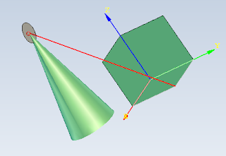
Magic point improvement
Improved the solver to detect magic points under mouse even if they are not on the current drawing plane.
On the picture below I started drawing a line on the base plane and could catch the cone top although I am not on that plane. This feature will also help at drawing "up" without helper geometry like the 3 initial planes.
On the picture below I started drawing a line on the base plane and could catch the cone top although I am not on that plane. This feature will also help at drawing "up" without helper geometry like the 3 initial planes.

Wednesday, December 15, 2010
Import/Export From NaroXml and What It Use?
Sometimes you did work to design a car, and you just did hardly a wheel. What can you do? You will copy/paste it and you will be ready to go. What if someone else did a car frame, you did the engine, and you want to combine your work?
NaroCAD had previously no way to do it. Right now two tools are ready to help you: Import from NaroXml which basically will do rebuild the shapes with re-based indices, and an export tool, which will save just the selected shapes.
Probably this will make easier sharing and will improve the way you design shapes by splitting your design in parts.
Tuesday, December 14, 2010
Version 1.5.4 Is Released
 Version 1.5.4 was released. It make review a lot of older issues and functionality that will make NaroCAD to run smoother, so more tools will work better:
- Added AngleDraft Tool: to make possible to chose the angle between two faces
- Added Rotate Around Axis Tool: you can have a more precise rotation than gizmos. Also gizmos are showing your shape transparent as you drag it. A dialog will point to you to write precise angle values.
- Added helper tools: copy and synchronizing tools between shapes: this will make easier to design repetitive designs or you want to make more tools to have consistent values all along.
- Added Rectangle with 3 points tool and added parallelogram tool: you will want a free hand rectangle? On any plane? A rectangle defined by three points is there. Also rectangle is kept internally as a parallelogram, making less prone to errors in case of transformations.
- Added Layout Saving Support: this will make easier to work with your custom layouts
- Added Edge on Edge constraint: based on fixes that were landed from previous iteration on transformations, we were able to spot and eventually enable a fixed Edge on Edge constraint
- Fixed Solver Bugs, enhanced its speed: when you iterate more shapes, OpenCascade will generate sometimes duplicate points. This consolidation was done because we wanted to trade the pre-compute time to real-time mouse movement, when moving mouse around should not be a slow operation as we check all scene points. We do consolidate them even from previous versions, but this algorithm was a bit slow as it checks all already existing points. This anyway had a big performance impact when you define a shape with many (more than hundreds) of points, the interface may freeze for minutes. Right now for very big point counts still some overhead is noticeable, but is two order of magnitude less for one thousand or more of points (like seconds, not minutes)
- Fixed unit tests: based on work of our contributor CyberDev our code is better tested mostly in plugin area. He works for his plugin and hopefully we will see more in his area.
- It was improved parametric modeling performance at File Load: we did change the way File Load is handled internally to reduce to minimum the loading of files: we clean the scene before we do our shape building, so it will also reduce the propagation cascade that happen for very similar scene changes
- Fixed propagation issues: opening files may make sometimes that for some tools that propagation to not work anymore
- Added center magic points at basic geometry (circle center, cone center, etc): you will have more magic points, in special on center of circle based shapes (both for sketch or solids)
- Gizmos can be selected from tree: so if you have an inaccessible shape, to drag it, you may use tree-view to select it, after it, you can see the gizmo to modify it. Also the shapes that you drag are transparent as you drag them.
- Property grid fixes: new handler code were done for the new tools of Rectangle/Parallelogram and fixes were also done.
Download from here.
NaroCAD Parametric Modeling Sample
Made a tutorial sample on how to use the parametric modeling features of NaroCAD together with Gizmos.
On the sample movie I selected from tree the rectangle on which an extrude is made or the circle used to make a cut. The shapes are invisible on scene but they can be selected in tree and Gizmos activate on them:
On the sample movie I selected from tree the rectangle on which an extrude is made or the circle used to make a cut. The shapes are invisible on scene but they can be selected in tree and Gizmos activate on them:
Angle Draft Tool
AngleDraft tool started working in most cases. From here we can start improving its usability.
A sample video:
A sample video:
Friday, December 10, 2010
NaroCAD 1.5.4 release plan
Last week worked at fixing and stabilizing the new functionality.
Currently NaroCAD 1.5.4 is almost at the stability level of the 1.5.3 version. In order to keep the quality at the level from 1.5.2 and 1.5.3 versions we'll continue testing and bug fixing for 2-3 more days. Planning to release the new version around Tuesday.
Currently NaroCAD 1.5.4 is almost at the stability level of the 1.5.3 version. In order to keep the quality at the level from 1.5.2 and 1.5.3 versions we'll continue testing and bug fixing for 2-3 more days. Planning to release the new version around Tuesday.
Angle Draft tool
Implemented the Angle Draft feature to demonstrate its usability. The feature is still very sensitive at the faces selected and also at their selection order, in many cases it doesn't work. Will be included in the next release version for demonstration purposes.
AngleDraft working case:
For the moment used a dialog box to set the angle as this was simpler to implement. After the feature will work well in most cases, will think on how to improve it as usability.
AngleDraft working case:
For the moment used a dialog box to set the angle as this was simpler to implement. After the feature will work well in most cases, will think on how to improve it as usability.
Improved rectangle dragging handles
The latest improvements at the rectangle tool allowed dragging handlers to be fixed and work well also when complex transformations are applied on it.
Editing a rectangle with several rotations applied on it:
Editing a rectangle with several rotations applied on it:
Monday, December 6, 2010
New Synchronize Tools
 As was already told, you can synchronize two tools values. Another handy tool is the Copy Deep Tool: you will use it to define a chain of tools from one shape on top of other shape.
A smaller version of it is just to apply one copy tool to another shape.
This will reduce property grid accesses and will reuse long and boring design works.
So enjoy using those tools.
Sunday, December 5, 2010
Syncronize Tool
A new tool was added to make easier modelling with various tools. The idea of it is simple: pick two extrudes and make sure that they share the same values. Another tool that will be done soon will be the one that you pick a source shape, and a destination shape, and all tools applied on the source tool will be set on the destination shape.
So stay tuned for updates!
So stay tuned for updates!
Friday, December 3, 2010
NaroCAD Team At Its Glory
 NaroCAD team is together in Timisoara/Romania where most of developers and contributors are here.
From left to right are: Samy, Mihai, Cristi and Ciprian (myself)
Thursday, December 2, 2010
Solver Extra Points, Rectangle Usage Improvments
Solver will generate center of circle, ellipse, arc, torus, cone and cylinder will offer extra points in center. Another improvement (with work from me and bxtrx) is that are two rectangle tools: the default two points defined, a ¨free¨ three points rectangle and a parallelogram.
Subscribe to:
Comments (Atom)
