Tuesday, March 31, 2009
Sketcher edit mode
Uploaded on SVN the code that allows editing the shapes drawn on the Sketcher. Dragging works, it needs to be stabilized because it has one bug: when more shapes are drawn the last shape drawn can't be edited, the others work fine.
Reviewed the action with pipes and filters code and started working at porting the
2d actions to this concept.
Will continue with finishing porting, add also the geometric solver when shapes are dragged, add displaying improvements.
Monday, March 30, 2009
Visual Studio 2005 discontinued and other changes...
Visual Studio 2005 Express Edition will disappear till tomorrow (without being the Foul Day's joke), so NaroCAD will not be suported to compile under this environment. And there is a good reason to upgrade: NaroCAD already uses Visual Studio 2008 features. SharpDevelop 3.0 or later can import nicely the NaroCAD project if you want an alternative environment!
There is a very interesting presentation about how may look the software in future by a chief designer at Adobe.
If you don't have an hour free to look to it the brief ideas are:
- use MVC (Model View Controller) as it separate the coupling and most of problems regarding your code. He said that for a simple dialog, he has 6000 lines of codes reflecting all interactions. He faces a lot the Spagetti Antipattern.
- enforce as much as you can from the language level (like using templates/constraints)
- use Pipes and Filters that makes the flow easier to be comprehensible
They succeed to do a minimalist MVC and a definition of Pipes and Filters in roughtly 2000 lines using widely templates.
The good faith makes that right now NaroCAD uses the same approaches. Accesing data from the model is done by taking the type you want, enforced by a template (we use Generics and Constraints). Without being too negative about C++, I can say that many parts of the NaroCAD code are really much concrete like:
- the Pipes and Filters system is: 350 lines of code
- the Model which is enforced is around 1000 lines of code
This means that with roughly a half of lines of code there is done more. The model knows how to do the Undo/Redo, it knows how to propagate changes, it knows how to enforce setting data in it and also it notifies also automatically.
The good point is also that the lines of code are decreasing (the assumption of him is that the lines decrease for 6 times, which may mean also that Adobe can have good drawing designers but bad software designers), but because we use specific OpenCascade code, events code which is already minimalistic in C#, etc. we gain reductions but not more than 50% of initial code size.
In weekend I've made a lot of enforcements and I finish them today. This means that all (3D) actions are ported with Inputs/Pipes. I have still problems to setup another plan and selection problems but I will fix them really soon. Today I've separated the coupling as there was in code a cast that makes presumtions about inputs. All of this are changed and data right now is sent and must be checked by the consumer. If I will find a nice way, I will try to do more on enforcing how data is send but without doing coupling.
One thing is still not fixed yet, but it will be very soon is that all 3D actions that do modify the scene, need to update the tree of objects, but they don't. Why? Because I should copy the code of updating the tree in actions. From now on, the actions will say: I need a tree view as an input, and I will say: UpdateTree. This will also make the code cleaner and adaptable. If tomorrow instead a Tree, there is a ListView, there is no problem, and at least we should not replace code more than 1 place: the action that provides the tree control.
Why coupling is very important to be avoided? In many cases developers wants code like: clicking on a button, the main window to be closed. They do at that time: Parent.Close(). Later, appears in the main menu the same option. Developers do the same code. Eventually, a toolbar action will need the same. Developer do the same.
For any reason, the application alegedly have a big start time, so the designers of the applications decide that instead closing the window, the window should be hidden and shown at a second launch. This will mean that the developer will have to replace all places of Parent.Close() with Parent.Hide(), but also, that seem to not be enough, as Parent.Show() have no sense, as Parent is coupled with the button, menu and toolbar action. Eventually the developer will separate the actions by the window, so eventually developer will call: MainWindow.Hide() and MainWindow.Show(). This doesn't seem a big deal for a 3 lines problem, (in 3 places to replace 1 line with another), but in most cases this overhead in code leads to copy/paste, and the worst of all, is hard to break the application flow easily. Coupling also leads to most programming errors in OOP programming at least: because everything knows about everything, the developer tend to break encapsulation (like putting some members of a class public) just to "simplify" the code.
Saturday, March 28, 2009
Pipes and Filters explained and working
I'm not completely sure how much I've explained why and what was changed.
The actions in 3D have a non uniform input code. This makes it really hard both to extend and to make things working in an environment like: multi-click because the click may have a completely different meaning. Also, some actions in 3D do not need a click at all: like (Top will setup the view to make things appear in top).
For that reason there was a need to be able to define different non uniform inputs to the actions to work with, that remains simple enough for the user. The multiple inputs have some limitations, like the most similar ones to share a very similar code. The most common case is the mouse click on a view: the simple click may mean many things: this click may have more meanings like:
- the point projected to a 3D plane, or even more, to be aligned to all closed geometry (so it should pass through a solver) when you draw a 2D shape like a line;
- or some actions can not use the 3D component at all, like to make a zoom to an area
- may look for the object which is under the mouse, or to extract the plane for it
For that reason, there is a pressing need for combining the inputs (to not duplicate code is another reason).At the end of the consuming of events stand the actions, which say which inputs and pipes are needed.
So, as a rough scheme: Input -> Optionally pipe -> Optionally pipe -> Action3D
Here is the code for a pretty complex action:
public class Line3D : Action3d
{
Mouse3dEventsPipe mouseIn;
ViewInput viewIn;
DocumentInput doc;
public Line3D()
: base("Line3D", new List() { "View", "Mouse3dPosition", "Document" })
{
}
protected override void OnSetup()
{
viewIn = Inputs["View"] as ViewInput;
mouseIn = Inputs["Mouse3dPosition"] as Mouse3dEventsPipe;
mouseIn.HasDataNotify += OnRecievedData;
doc = Inputs["Document"] as DocumentInput;
}
public override void Deactivate()
{
base.Deactivate();
mouseIn.HasDataNotify -= OnRecievedData;
}
List points = new List();
void OnRecievedData(Object data)
{
(...)
So from scratch this action can change only the View, Mouse3dPosition and Document.
Mouse3dPosition is a pipe, and Naro API knows its dependencies and tracks them and makes a chain till all of them are connected. Because of that, there is no need for the user to create all the things and to connect them, this thing is done automatically.
Also, in the past was not done, but right now it is, the actions have a deactivate code, this will prevent actions from remaining in an uncertain state at any moment, no matter is canceled or so. This avoids a lot of cases of leaks.
Also, the deactivate cleans automatically all links and break the graph of Inputs and Pipes, it makes the Inputs ready for the next action.
Was it worth doing?
Both in short and long terms it was: it is possible almost to not a single code to create a brand new action without a copy, it is possible to give a (new) meaning to mouse click, the code is safer (as there is a Deactivate method) and also less prone to errors (as it works with less components that need to be saved).
Based on the last two weeks refactor, it enables NaroCAD to work with a new infrastructure, it is of a much higher level than the previous code, it is better detached, it propagates automatically the events, it is debuggable. The actions don't do copy-paste both in 2D and in 3D to achieve a multi-click action.
Anyway, the single action in 3D that works with multiclick is Line for now. I will continue to work for the others. Also, I would like to add the possibility that if mouse stands on a face for more than 3 seconds, to be selected as the face to be drawn.
As there are many refactored parts, I will try also to write documentation to this so if you feel courageous a bit and you like C#, and you want to look a bit at OpenCascade, it will be a great start to extend the NaroCAD code. It will let you to use NaroCAD as the base software and extend it where you need it.
What is the achievement over the last three weeks of refactor?
Based on the fact that you will also get scripting possibility pretty soon, you can extend in NaroCAD almost everything: data storage (as attribute data that can be extended to any component), business logic (tree attributes interpreters), custom shapes (as functions, that are simplified greatly to work with, and all changes are tracked automatically by NaroCAD framework), view presentation (as actions).
Note: NaroCAD also has a debug window (in case you did not know it) that makes almost instant navigation to the scene tree.
The actions in 3D have a non uniform input code. This makes it really hard both to extend and to make things working in an environment like: multi-click because the click may have a completely different meaning. Also, some actions in 3D do not need a click at all: like (Top will setup the view to make things appear in top).
For that reason there was a need to be able to define different non uniform inputs to the actions to work with, that remains simple enough for the user. The multiple inputs have some limitations, like the most similar ones to share a very similar code. The most common case is the mouse click on a view: the simple click may mean many things: this click may have more meanings like:
- the point projected to a 3D plane, or even more, to be aligned to all closed geometry (so it should pass through a solver) when you draw a 2D shape like a line;
- may look for the object which is under the mouse, or to extract the plane for it
For that reason, there is a pressing need for combining the inputs (to not duplicate code is another reason).At the end of the consuming of events stand the actions, which say which inputs and pipes are needed.
So, as a rough scheme: Input -> Optionally pipe -> Optionally pipe -> Action3D
Here is the code for a pretty complex action:
public class Line3D : Action3d
{
Mouse3dEventsPipe mouseIn;
ViewInput viewIn;
DocumentInput doc;
public Line3D()
: base("Line3D", new List() { "View", "Mouse3dPosition", "Document" })
{
}
protected override void OnSetup()
{
viewIn = Inputs["View"] as ViewInput;
mouseIn = Inputs["Mouse3dPosition"] as Mouse3dEventsPipe;
mouseIn.HasDataNotify += OnRecievedData;
doc = Inputs["Document"] as DocumentInput;
}
public override void Deactivate()
{
base.Deactivate();
mouseIn.HasDataNotify -= OnRecievedData;
}
List points = new List();
void OnRecievedData(Object data)
{
(...)
So from scratch this action can change only the View, Mouse3dPosition and Document.
Also, in the past was not done, but right now it is, the actions have a deactivate code, this will prevent actions from remaining in an uncertain state at any moment, no matter is canceled or so. This avoids a lot of cases of leaks.
Also, the deactivate cleans automatically all links and break the graph of Inputs and Pipes, it makes the Inputs ready for the next action.
Was it worth doing?
Both in short and long terms it was: it is possible almost to not a single code to create a brand new action without a copy, it is possible to give a (new) meaning to mouse click, the code is safer (as there is a Deactivate method) and also less prone to errors (as it works with less components that need to be saved).
Based on the last two weeks refactor, it enables NaroCAD to work with a new infrastructure, it is of a much higher level than the previous code, it is better detached, it propagates automatically the events, it is debuggable. The actions don't do copy-paste both in 2D and in 3D to achieve a multi-click action.
Anyway, the single action in 3D that works with multiclick is Line for now. I will continue to work for the others. Also, I would like to add the possibility that if mouse stands on a face for more than 3 seconds, to be selected as the face to be drawn.
As there are many refactored parts, I will try also to write documentation to this so if you feel courageous a bit and you like C#, and you want to look a bit at OpenCascade, it will be a great start to extend the NaroCAD code. It will let you to use NaroCAD as the base software and extend it where you need it.
What is the achievement over the last three weeks of refactor?
Note: NaroCAD also has a debug window (in case you did not know it) that makes almost instant navigation to the scene tree.
Thursday, March 26, 2009
Line in 3D and other changes
Actions in 3D passed a big refactor that make possible adding 3D shapes based on 3D clicks. And the code nicely remains the same when is possible like the code in 3D.
What does accomplish?
The modeller component defines inputs and an action may connect optionally to one or more inputs. Second thing, is that on top of inputs, there can be build a concept named pipe.
What is a pipe? Is an input on front of other input. The 3d coordinate is for instance translated from a 2D coordinate, an OpenCascade view and a plane that is projected the mouse.
What brings from the level of future code on matter of usage? By using pipes, it is easy to insert solver without making over-design or change the code or dependencies. Also, it does not make a mess in case that one action, like a simple view action (Fit All, or Top view) to interpret the mouse in 3D. Also, by directly stating the dependencies, will make actions to not modify the components that don't have sense. In the past a Zoom action may be able to change the document, and may be not wanted. A future Save action may change the document and the view, but not relate on mouse, etc.
Based on that, after a review, most probably the actions will be more unified, and for sure the code is in the last straight to work multi-clicks (as is intended for this iteration).
Wednesday, March 25, 2009
Refactor and fixes
The actions in 2D mode was refactored to work with multiple clicks instead dragging and dropping. The refactor of 2D actions is really good, as it separates the actions which process the view from actions which work with shapes, and in the future there will actions that will edit the shapes.
Anyway, going to 3D things is more complex: as far as I've looked there are multiple sources that defines an action, and roughly for now they are:
- actions that model the view
(and here are actions that create a real shape: )
- actions that are 2D and work in 3D, so they will work projected in a plane, which plane needs to be changed
- actions that work in 3D directly with 3 or more clicks
- actions that work with a shape, and processing (like extrude)
On second thoughts, the code of 2D actions is not enough, because for now the actions are limited yet to a number of clicks and this is all, and the actions may have clicks or mouse move almost exclusively. One limitation (that will be fixed over in the future) is also that the solver should adapt basing on the selected plane. And for other actions it will not be used.
So the limitations of the 2D actions are the following:
- the action itself should handle a lot of the input code because the events are simple (clicks)
- the custom plane should be fixed outside the action by the user in an invisible way (for now my code is with predefined planes, but the user should be able to select a face, and to edit on it, and it will work)
- the actions should be able to treat multi-actions open-ended clicks (like polylines... where the action knows "when to stop")
- the actions may want to have the solver with different behaviors corresponding with the plane or rules, but only in some actions.
Most of limitations rely on how the input is generated. It can be generated in every possible way: it may be a shape, simply the view that it applies to, a double stating the width of the extrude, etc. Another limitation is that an action can never reply it's status, if you select a line, the line keeps the track of all mouse inputs, and it tries to create things depending on the first or the second point selected.
What is the plan?
The next step is to separate the input code OUT of the actions code. The code will still have some code that asks for a separate input, but it will do something like this: asks for a shape, asks for a double, do the extrude or: asks the first point, the current selected plane, the second point, and based on that, it will do a line. Also, this leads to a possibility to not make hacks to select another plane or to be sure that one is selected. Probably the code will be similar in future with Functions' dependencies code, but this is not such a easy to do task for now.
Sunday, March 22, 2009
Small usability fixes...
Till today I've did two things:
- I looked for the next big changes for actions 3D with Mihai. I had start to look the implications and I've did a review of 2D actions already made by Mihai
- the actions are much easier to be defined as other mouse buttons than the left one are used to make pan or zoom for 2D, and rotate and pan for 3D
- other small fixes
We will see in the next days what will appear... stay tuned!
Saturday, March 21, 2009
Magic points detection and display
Added the geometric solver and made it work. Wrote the code that displays the magic points, also made some classes that build the magic point displayed shapes. For the moment end points and mid points are detected and signaled using a red circle. After the geometry edit mode will be finished will improve the solver to display different symbols for different types of magic points (something like: circle for end point, triangle for mid point).
Will continue to work today and tomorrow at adding the edit mode for the sketched shapes. One problem that stops me is that the drawn shapes are not selectable, will have to solve this problem first.
Friday, March 20, 2009
Sketcher fixing
Worked at putting together the Sketcher functionality. The drawing works with user clicks, the tools like pan, zoom are working properly. Made a code commit and there are no functionality conflicts. Tomorrow will continue with adding the geometric solver and the display of magic points.
Started also implementing the code for drawing shapes on 3d.
Automatically propagation much faster
In the last days I've faced a hard to find bug as most of the functionality seems to be correct therefore it was harder to check, as the single symptom was that the things went from slow to much slower.
The problem was that every time before a function to execute, the function checks the dependencies of it and registers (in a bogus way) to them again. In the result, the more you use it the more the function will be called. In case of using multiple dependency functions as: a rectangle is the base of extrude, makes like: 9 x 7 calls, which makes the extrude to be executed for 63 times, at the second call was like 10 x 8 = 80 times, etc.
Right now the extra calls may happen from a user’s code, like not using the BeginUpdate method. This will call a function at every dependency change. But this is a usage problem, not a Naro API problem.
I will use right now the power of Naro API to update the tree automatically on the basis of tree changes and to show the references of every shape, as a child of this shape.
Thursday, March 19, 2009
Sketcher refactoring
Finished refactoring the sketcher drawing. Will continue now with adding the edit mode for the geometric objects and when finished will start adding the geometric solver and the magic points. Planning for tomorrow evening to commit the code with properly functioning drawing and editing.
Automatically propagation (Parametric modelling) working
Automatically propagated events are working. Still there are too many called events (a thing I will look more for fixing). In the past, the code was like this: we mark the things that was changed, and we visit the tree of OCAF and we mark in another step things that may be modified from changes (and the code did not always work right). Right now, because a function have dependencies, if any dependency was changed, the function is notified and regenerate a shape.
Use case that works nice right now:
- create a rectangle, extrude it
- pick the rectangle in the OCAF tree
- change width and should resize the depending extrude
Still the changes seems to lag, and this is because there are many notifications that are not filtered or a bug. I work to find the cause!
Wednesday, March 18, 2009
Sketcher refactoring
Still working at refactoring the Sketcher when drawing with mouse clicks instead of mouse dragging. Will try also to implement the edit mode using actions for a better code separation. Tasks estimated to take one more day of work.
Bug fixing...
Still working around the bugs of automatic propagation of the changes. over the dependencies. There will be a locking mechanism to reduce the unnecessary changes. For now code not committed yet, changing of the width of a rectangle will build the rectangle twice, which is neither needed nor wanted. So every function will have a BeginUpdate method that will lock the updates till an EndUpdate or Execute happens. This will make the events events less cluttered up. Also, the notifications will auto-create the visual geometry (AIS Shapes) after every function has been called. This code works but is not committed (again) because the functions that generate the base shape are not running well.
Monday, March 16, 2009
Started iteration 0.0.9
The tasks scheduled for the current iteration are:
- Rebuild the tree view logic to display references as child nodes, estimated 6 hours,
- Apply on the tree view the model tree changes, estimated 3 hours,
- Propagate tree modifications (parametric modeling for the new data tree), estimated, 1 day,
- Extrude improvements, estimated 2 hours,
- Port Action2D to work with multi click instead of dragging, 1.5 days,
- Port Action3D to work with multi click instead of dragging, 1.5 days,
- Extract 2D actions drawing code to work in 3D (ex: drawing a line in 3D), estimated 4 days,
- Make the geometry solver to work with the data tree, store solver attributes on the data tree, estimated 3 days,
- Add code that displays magic geometry, estimated 1.5 days.
On the iteration will be made also code refactoring, bug fixing and documentation update.
Sunday, March 15, 2009
Changed mouse drag with mouse click
Refactored the 2d actions to work on click not on mouse drag. Moved the geometric solver out of the actions, this will be an independent entity. Made the draw line action work properly on clicks.
Will continue integrating the solver with the drawing operations so that the magic points are displayed while drawing. Will also work at making the other actions work with clicks instead of dragging and also integrate them with the solver.
From tomorrow will also start working on iterations, will prepare the tasks and estimations for the iteration 0.0.9.
Saturday, March 14, 2009
Port is (almost) complete
The porting of OCAF Tree to the NaroData.Node is done. At least works functionally equivalent with old implementation. Some things are missing still, but it starts, and runs (well).
The other achievement is how is the Action2D and Action3D are done. They are use directly the defined Dependency (in past was named as Schema) and they not work against the nodes. This will make that most complex actions to not write nodes that do not belong to their predefined usage.
So this is the new extrude code (which is a pretty complex action):
public static void Extrude(Node L, Node shape, double extrusionHeight, ExtrusionTypes extrusionType)
{
FunctionInterpreter function = L.Update<FunctionInterpreter>();
function.Name = "Extrude";
// Attach the shape on which the Extrusion is applied as the first child label
function.Dependency.Child(1).Reference = shape;
// Add the extrusion height as a second child label
function.Dependency.Child(2).Real = extrusionHeight;
// Add the Extrusion Type as a third child label
function.Dependency.Child(3).Integer = (int)extrusionType;
L.Update<StringInterpreter>().Value = DisplayedShapeNames.Extrude;
if (function.Execute() != 0)
{
// TODO: Handle the error
}
// Attach an integer attribute to L to memorize it's not displayed
L.Update<IntegerInterpreter>().Value = (int)OcafObjectVisibility.ToBeDisplayed;
}
The old code?
public static OCTDF_Label Extrude(OCTDF_Label rootLabel, OCTDF_Label shape, double extrusionHeight, ExtrusionTypes extrusionType)
{
// Create a new child label on which the extrusion Label structure is generated
OCTDF_Label L = OCTDF_TagSource.NewChild(rootLabel);
// Attach the shape on which the Extrusion is applied as the first child label
OCTDF_Reference.Set(L.FindChild(1, true), shape);
// Add the extrusion height as a second child label
OCTDataStd_Real.Set(L.FindChild(2, true), extrusionHeight);
// Add the Extrusion Type as a third child label
OCTDataStd_Integer.Set(L.FindChild(3, true), (int)extrusionType);
// Add the operation name
OCTDataStd_Name.Set(L, new OCTCollection_ExtendedString(DisplayedShapeNames.Extrude));
// Instanciate a TFunction_Function attribute connected to the extrude driver
// and attach it to the data structure as an attribute of the Extrude Label
OCTFunction_Function.Set(L, OCAFExtrudeDriver.Guid);
// Initialize and execute the Extrude driver
OCTFunction_Logbook log = new OCTFunction_Logbook();
OCAFExtrudeDriver extrudeDriver = new OCAFExtrudeDriver();
// Find the ExtrudeDriver in the TFunction_DriverTable using its GUID
if (!OCTFunction_DriverTable.Get().FindDriver(OCAFExtrudeDriver.Guid, extrudeDriver, 0))
return null;
extrudeDriver.Init(L);
if (extrudeDriver.Execute(log) != 0)
{
// TODO: Handle the error
}
// Attach an integer attribute to L to memorize it's not displayed
OCTDataStd_Integer.Set(L, (int)OcafObjectVisibility.ToBeDisplayed);
return L;
}
The difference is in details, but the point is that the code is moved to the new infrastructure.
Line is not a driver, but is a function
Yesterday I said that OCAF code is to be replaced. At that moment the code that creates shapes (TopoDS_Shape) was a part of the OCAF tree but right now is removed. The code is mainly the same, and the code is ported to the new infrastructure. I was blocked a bit by a tricky build issue (thanks bxtrx for fix!).
How do you add an extra shape?
Define the dependency that says which data is needed for your shape:
public class LineDependency : DependencyBase
{
public LineDependency() : base("Line")
{
AddAttributeType(1, "Geometry");
AddAttributeType(2, "Geometry");
}
}
This class say that a line will need two geometry points, defined as children 1 and 2.
The OpenCascade function that defines your shape is the following:
public class LineFunction : FunctionBase
{
public LineFunction() : base("Line")
{
Dependency = DependencyFactory.Instance.GetDependency();
}
public override int Execute()
{
// Get the values of dimension and position attributes
OCgp_Pnt firstPoint = Dependency.Child(1).Geometry;
OCgp_Pnt secondPoint = Dependency.Child(2).Geometry;
OCTopoDS_Edge aEdge = new OCBRepBuilderAPI_MakeEdge(firstPoint, secondPoint).Edge();
var shape = new OCBRepBuilderAPI_MakeWire(aEdge).Wire();
var shapeInterpreter = Parent.UpdateInterpreter();
shapeInterpreter.Shape = shape;
return 0;
}
}
And before using any of them, register them to be known globally:
DependencyFactory.Register();
FunctionFactory.Register();
How do you add an extra shape?
Define the dependency that says which data is needed for your shape:
public class LineDependency : DependencyBase
{
public LineDependency() : base("Line")
{
AddAttributeType(1, "Geometry");
AddAttributeType(2, "Geometry");
}
}
This class say that a line will need two geometry points, defined as children 1 and 2.
The OpenCascade function that defines your shape is the following:
public class LineFunction : FunctionBase
{
public LineFunction() : base("Line")
{
Dependency = DependencyFactory.Instance.GetDependency
}
public override int Execute()
{
// Get the values of dimension and position attributes
OCgp_Pnt firstPoint = Dependency.Child(1).Geometry;
OCgp_Pnt secondPoint = Dependency.Child(2).Geometry;
OCTopoDS_Edge aEdge = new OCBRepBuilderAPI_MakeEdge(firstPoint, secondPoint).Edge();
var shape = new OCBRepBuilderAPI_MakeWire(aEdge).Wire();
var shapeInterpreter = Parent.UpdateInterpreter
shapeInterpreter.Shape = shape;
return 0;
}
}
And before using any of them, register them to be known globally:
DependencyFactory.Register
FunctionFactory.Register
Friday, March 13, 2009
Drawing helpers
Started implementing a drawing helper module that detects magic points and establishes relations between them (center of a line, line parallel with another line, etc). This will be integrated at first on the Sketcher module (for 2d drawing) and it will then be integrated also in the 3D part.
In parallel with this will also change the user actions to use clicks instead of mouse down mouse up.
OCAF Code is gone. Did It Worth?
How does an OpenCascade application using OCAF work? OCAF applications are MVC applications applications, where there is a storage layer (the Model) that stores the data needed to keep the entire scene. There is an OpenCascade view that displays a list of AIS_InteractiveObjects which are built directly from the OCAF data. And in between there is a NaroCad (or any other application code) code (Contoller).
We’ve decided to get rid of OCAF code.
Why?
- OCAF code is C++ code, and makes it almost impossible to debug it using the Visual Studio debugger (we debug it by displaying it visually, but we don't have other ways)
- OCAF structure forces us to work with GUIDs and makes it also very hard from C# level to extend it easily
- OCAF has no attribute for colors, or other .NET types. We stored till now as an IntegerArray attribute to the interesting nodes.
- TFunction (shape generators that make the parametric modeling working) code is really clumsy and we need to iterate over entire OCAF Tree and do a lot of things manually
- last but not least: there is no obvious way to get notified when data was changed (or its dependencies)
OCAF have nevertheless some good design decisions that we wanted to keep, as the labels (the OCAF tree nodes) are indexed by integers. This makes locating a tree path pretty fast and with minimal code. Another one is that the attributes are stored unique per node. So there cannot exist two integers under the same label.
What does the implementation bring as being C# only?
- A cleaner API:
Every node has a Children property exposed, which is a SortedDictionary (where Node is the TDF_Label replacement). This makes it clear to the user that it can iterate over the nodes.
The new code to iterate children is the following:
foreach(Node child in label.Children.Values)
{
//code using the current child node
}
- we use Generics to access the node attributes:
If we want to modify an integer value to a tree node, the code is the following
L.UpdateInterpreter().Value = (int)OcafObjectVisibility.ToBeDisplayed;
Another custom attribute that is the base of parametric modeling functions:
FunctionInterpreter function = L.UpdateInterpreter();
function.Name = "Extrude";
function.SetNode(L);
if (function.Execute() != 0)
{
// Handle the error
}
An easy way to add a custom attribute:
public class IntegerInterpreter: AttributeInterpreterBase
{
public IntegerInterpreter() : base("Integer") {}
public int Value { get ; set; }
}
And before using it, you should call AttributeDataFactory.Instance.RegisterInterpreter();
The attributes may get more complex, but this is the whole idea!
Code implications:
- in 90% the code is shorter, but in 100% the code is cleaner
- code completion and debugging works over the place
- refactor that implies 70 files
- potential problems for 2-3 days in NaroCad codebase
Note: we did replicate not only the OCAF tree storage, but also (as it was needed) the OCAF Document functionality, so if someone will want to use NaroCAD storage model, will have the entire support for doing this. This may make NaroCAD a very C# friendly CAD development platform, and for sure one step beyond the past.
We’ve decided to get rid of OCAF code.
Why?
- OCAF code is C++ code, and makes it almost impossible to debug it using the Visual Studio debugger (we debug it by displaying it visually, but we don't have other ways)
- OCAF structure forces us to work with GUIDs and makes it also very hard from C# level to extend it easily
- OCAF has no attribute for colors, or other .NET types. We stored till now as an IntegerArray attribute to the interesting nodes.
- TFunction (shape generators that make the parametric modeling working) code is really clumsy and we need to iterate over entire OCAF Tree and do a lot of things manually
- last but not least: there is no obvious way to get notified when data was changed (or its dependencies)
OCAF have nevertheless some good design decisions that we wanted to keep, as the labels (the OCAF tree nodes) are indexed by integers. This makes locating a tree path pretty fast and with minimal code. Another one is that the attributes are stored unique per node. So there cannot exist two integers under the same label.
What does the implementation bring as being C# only?
- A cleaner API:
Every node has a Children property exposed, which is a SortedDictionary (where Node is the TDF_Label replacement). This makes it clear to the user that it can iterate over the nodes.
The new code to iterate children is the following:
foreach(Node child in label.Children.Values)
{
//code using the current child node
}
- we use Generics to access the node attributes:
If we want to modify an integer value to a tree node, the code is the following
L.UpdateInterpreter
Another custom attribute that is the base of parametric modeling functions:
FunctionInterpreter function = L.UpdateInterpreter
function.Name = "Extrude";
function.SetNode(L);
if (function.Execute() != 0)
{
// Handle the error
}
An easy way to add a custom attribute:
public class IntegerInterpreter: AttributeInterpreterBase
{
public IntegerInterpreter() : base("Integer") {}
public int Value { get ; set; }
}
And before using it, you should call AttributeDataFactory.Instance.RegisterInterpreter
The attributes may get more complex, but this is the whole idea!
Code implications:
- in 90% the code is shorter, but in 100% the code is cleaner
- code completion and debugging works over the place
- refactor that implies 70 files
- potential problems for 2-3 days in NaroCad codebase
Note: we did replicate not only the OCAF tree storage, but also (as it was needed) the OCAF Document functionality, so if someone will want to use NaroCAD storage model, will have the entire support for doing this. This may make NaroCAD a very C# friendly CAD development platform, and for sure one step beyond the past.
Monday, March 9, 2009
New installer and code cleanup
NaroCAD has an installer script on SVN. It is based by InnoSetup, it require to you to have preinstalled the following components:
- .NET 3.5 SP1
- Visual C++ 2008 SP1 Redistributable Runtime
- OpenCascade (that may be downloaded from the www.opencascade.org
after you create a new account to your site)
Requirements: Windows XP SP2 or newer, Windows Vista or Windows 7 beta.
Download it from here
This installer may make easier to test in future NaroCAD and is pretty small (4.5 MB).
As the code will need some reorganization, the code is lightly cleanup. The schemas that enforce the data access were moved from function-drivers component to outside so any other component may use the schemas to not access wrong data.
How does a schema work? A schema will set a list of children and attributes. The children are numeric, and the attributes are a string from predefined sets.
So how is defined a schema that defines a line? It is defined as a two-point schema, the first is kept in child 1, the other one in child 2. The code is as following:
public class LineSchema : DescriptionSchema
{
public LineSchema() : base("Line")
{
AddAttributeType(1, "Geometry");
AddAttributeType(2, "Geometry");
}
}
How is used in our OCAF driver that define a line?
public class Line : DriverSimple
{
public Line() : base(2)
{
schema = SchemaFactory.GetSchema("Line");
}
public override OCTopoDS_Shape Execute()
{
// Get the values of dimension and position attributes
OCgp_Pnt firstPoint = schema.Root.Child(1).Geometry;
OCgp_Pnt secondPoint = schema.Root.Child(2).Geometry;
OCTopoDS_Edge aEdge = new OCBRepBuilderAPI_MakeEdge(firstPoint, secondPoint).Edge();
return new OCBRepBuilderAPI_MakeWire(aEdge).Wire();
}
}
This code will clean your code that was accessing your OCAF tree, it also guarantees that you will not read outside of that 2 points (or depending on your schema, the type of geometry you want to access), or reading other attributes that are not defined!
Thursday, March 5, 2009
Small updates on interface
Naro have eventually separated the all Part Modeler actions as separate classes. Fillet works lively but a bug stops it to be visible to user but this is gonna to be fixed.
Some other small changes that you may enjoy:
- NaroCad starts directly to do Part modeling, so no extra clicks on that
- the sketcher remembers it's last tool, so is much easier right now to draw multiple rectangles
Some other small changes that you may enjoy:
- NaroCad starts directly to do Part modeling, so no extra clicks on that
- the sketcher remembers it's last tool, so is much easier right now to draw multiple rectangles
Wednesday, March 4, 2009
Magnetism around...
If you worked with a tool that does design, one of the most used features is to create shapes with exact sizes. For this in NaroCAD you may use the grid. But there are some cases you will not get enough with that. So there is a need to consider other cases like: - middle of a line, the bounds of a line, or corners of a rectangle, etc. The solution should be specific enough and generic enough also.
Right now enters in scene a new Naro compoment: the Solver. What should this solver do? It should have a set of geometry and some rules that can make processing on top of that geometry. In future it may compute the interesting geometry beyond the points, as like shape constraints, etc.
Where is this solver used? When you input your values, the solver may offer the right values to you, or it may give to you the closest point that is interesting to you, or all points. The future extensions of solver may make Naro offer more visual hints to the user.
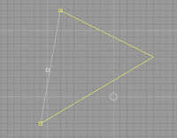
Where is the solver used right now? The solver right now processes the interesting line points and aligns the mouse to them (magnetic points). So at least is easy to draw a triangle made by three lines right now in Naro, without a grid.
Solver design (look to picture):
The solver consists of 2 components:
- a geometry tree (that resembles OCAF tree: a tree of nodes indexed by integers and a list of unique attributes, identified by a string)
- a RuleSet that can process the geometry tree
The RuleSet may be changed depending on geometry and needs. So if you add more rules, you will get a more complete solver.
The solver may be queried every time to give the most interesting geometry closed by a defined point, and it makes it easy to make mouse align to the returned solver geometry.
Tuesday, March 3, 2009
C# 3.0 features that clean up (a bit) the code
I work to a new feature (so stay tuned!) but I wanted to describe some features that are used in NaroCad and are specific to C# 3.0 (part of .NET 3.5 and Visual Studio 2008).
We don't use LinQ and lambda expressions for now but some features may interest other developers when they have to handle our code:
1. The var keyword
Old code
SortedDictionary<int,Node> _childNodes = new SortedDictionary<int,Node>();
New code:
var childNodes = new SortedDictionary<int,Node>(); (the compiler will decide the type, and the code is equivalent)
var removes a long left side declaration and it is shorter than most types you can define. The issue is that using var keyword extensively you will not be able to decide which type you run.
var x = f(); //where f returns a type int
x = 3.1415; // it will give to you a compile error as you want to use it as a float type
//but is declared as int
2. Automatic created properties:
Old code:
class Line2d
{
...
public Vertex3d Vertex1
{
get {return _vertex1; }
set { _vertex1 = value; }
}
//internal member class to reflect the properties
Vertex3d _vertex1;
}
The new code is only this:
class Line2d
{
...
public Vertex3d Vertex1 { get; set; }
}
If you will know other tricks or hints, add comments down!
Sunday, March 1, 2009
Live Update for Extrude
This is gonna be short, but is an important achievement. Extrude works lively and works nice: Click on a shape you want to extrude and dragging the mouse up-down you increase/decrease the extrude size. This is the first complex action that works lively and it is based on different working that was done last week.
What will be next:
- bug fixes (the ellipse is still not fixed in all cases)
- fillet to work lively also
- code organization to make easy adding a new action 2D or 3D.
Subscribe to:
Posts (Atom)