Monday, January 31, 2011

Block Drawing Plane

This command allows the user to block the drawing plane by selecting a surface. The idea is to block the current drawing plane, so that all shapes that are to be drawn should be generated only in the desired plane. If this tool is not activated, the drawing plane changes as the user moves the mouse over surfaces or solid faces.
Block drawing plane works like this:
- The user presses the "Block Drawing Plane" button
- The user selects a surface / does nothing
The selected surface should be planar. NaroCAD tries to extract the normal line of the selected surface. If it fails, the blocked plane will be the last one used. If the user selects an invalid surface from the very beginning, NaroCAD will set the drawing plant to the XOY plane. The user also has the option to simply push the "Block Drawing Plane" button, without selecting any other shape. As expected, NaroCAD will block the last defined plane.
Notice that the solver points have bigger priority compared to this tool. This means that solver endpoints will work even if the block plane is activated. For example, if the user starts a line and selects the first point as the endpoint of another line that is not in the current drawing plane, that point will be recognized as valid. If the second point is not generated with the help of the solver, it will be generated in the drawing plane.
The last thing to mention is the difference between the activated and non-activated drawing plane. When the user blocks the drawing plane, the "Block Drawing Plane" button will change its background color to red, and its text to white. This way, the user knows when this tool is active. Deactivating it will return its colors to default.

You can test this new tool by downloading the last nightly build from www.narocad.com, under the download section.

Sunday, January 30, 2011

Some Changes

I've did working on a new Spline some changes as were noticed as missing. They are more or less like a bugfixing/features completeness and they are in short:
- Boo expressions will work for integer based expressions
- almost all cases (excluding cases that can work with impracticable large shape count) will update tree-view correctly. As code level some cases will get easier to make populating this code easier to do (it can be defined a root node, and all nodes will be added in cascade)

Wednesday, January 26, 2011

NaroCAD 1.5.6 Released

- TreeView speed improvement for big scenes - all simple shapes will do minimal updates on tree view
- Boo script evaluator on property grid, command line - input is evaluated thought the Boo compiler making possible to use sine, cosine, operators, parentheses, and so on,
- Scene export as Boo script - to make transition to future versions and integrating with Boo code easier
- Linear pattern - an advanced yet simple to use pattern over a line
- Circular pattern - an advanced yet simple to rotate a shape and clone it over a line
Support for composed shapes from basic shapes - to make possible to make regular or shapes depending on other shapes easy
- Fixed mirror - solids will mirror nicely by using right OpenCascade code to do it
- Fixed color picker, solver hint positioning - so you will enjoy even more using NaroCAD

Download it from here.

Update: we have problems with SourceForge hosting so we put it on alternate link. Please refollow the download site and we will use NaroCAD site till SF will work back reliable.

Tuesday, January 25, 2011

Fixed mirror tools

On last two days studied OpenCascade shape topology especially because the mirrored shapes had some "inside out" look.

Made a change at the TopoDsShapeInterpreter that affects the way that all shapes generated on scene are built. It seems to work well. On the interpreter we're now using BRepBuilderAPI_Transform to apply transformations on all generated shapes.
Fixed also the mirror point/line/plane tools. Visually the shapes look ok.
We don't fully understand yet how OpenCascade generates shapes in cases like mirroring (with a reversed local coordinate system and a transformation on them), in time this area will be improved.

Array Pattern

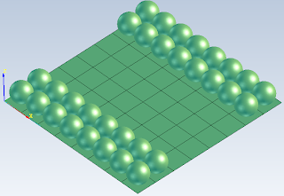
Array Pattern is now finished. The user can now draw an array of objects as described in the earlier post. The attached image shows array pattern in action. The board was generated with the help of one of the initial rectangles. for the sphere, 2 array pattern were used, each with 2 rows and 8 colomns.
Be careful though, because array pattern is made in the current drawing plane. This means that hovering the mouse over surfaces or faces, might change the drawing plane without giving any warning :P
The array pattern is available in the last nightly build. Please post on the forum if you want to comment about anything about it.

Monday, January 24, 2011

Boo-gfixes and updates

As my previous development was more or less related with Boo integration (and some other development, mostly on fixing) Samy found on usage some bugs and here are those fixes:
- Boo will have an option to evaluate (or not) your double based values. This will bring faster response time when you will input values (because to evaluate 5+5 will mostly imply a small class compilation)
- when Boo Gear was made some Boo compiler bugs were encountered which makes NaroCAD to take the version their Git. This made that the old Boo compiler version accepted a construct (that after review, I found that was a mistake) and the new version give correctly a compiler error. This affected using Export to Boo plugin so I've fixed this
- BooView for this very reason will not enable the Execute button when compiler error are pending. This will remove the annoyance and discomfort for people did not look down and make a small typo and will be bombarded with Boo messages. Anyway, if you're fast, you can still get them (like writing ; and go as fast as possible to Execute button before is disabled)
- solver's visual hints were bad placed, so I've found why: the TextOut method in OpenCascade API seems to not position them right on the coordinate, but is sensible also to the width/height factor, so this is fixed now :)

Array Pattern - first steps

I started to implement the array pattern command. It can be used to make something similar with a chess board.
Before starting the command, the user will select the desired object to pattern and a direction. It seems pretty normal that array pattern should work in a plane. This is why I will use current drawing plane as the pattern plane(without asking the user). So, be careful with the drawing planes. But still, the drawing plane is not enough to even start the command. It is pretty obvious that the rows have some king of direction; the same goes for the colomns. this is why I will ask the user to select the row direction. Still, I will not ask the user to select the colomns direction because it must be perpendicular with the rows direction. So, NaroCAD will do it for you. 4 more parameters are: the number of rows and colomns and the distance between the objects(row distance and colomn distance).
The row direction will depend on how the line is drawn: from the first point, to the second point. Due to the fact that the patterned objects might not appear in the desired direction, I added 2 check-boxes in order to allow the user to reverse the desired direction, if necessary.
With this functionality, I hope that I covered everything a user needs in order to make an array pattern. If you have any new ideas, or wish to ask questions about this command, do not hesitate to post on the forum. The command will be available tomorrow in the last nightly build.

Friday, January 21, 2011

Boo Shapes Plugin (Part IV)

And the last part. Probably for a regular polygon (and a gear) seems to be described in too many blog posts. Anyway, they do stress development in the idea that NaroCAD will have more external code in its package. Library shapes infrastructure support was the next logical and I will explain it using this shown diagram.
Let's say you will want to draw an OpenCascade shape: you will have to define a function that draws the topological shape, after this an action will use a NodeBuilder to instantiate it, to create it's corresponding shape, to set up extra attributes and at the end will put it in document.
A LibraryShape implementation works in a similar way with a Function (a shape generator) but instead using low level OpenCascade calls, will use Functions and will do it by using directly NodeBuilder and document.
So in this manner actions can take one step further and generate complex shapes on top of already existing shapes in NaroCAD (mostly as shapes are any item you will see on your tree of objects).
As Functions wrap OpenCascade code (so it need to be written just once!), they will need a component to get parameters. This component is the dependency part: this will make notifications automatically. So you will get both shape generation and propagation for free.
A library Shape will have dependencies, or arguments, but they will simply mean a creator framework. So a gear is simply defined as: tooth count, smaller range, bugger range and extrusion value. A regular polygon is defined as two points (center, the second to define its range) and the edges count.
Both will iterate and create the result combining functions (in both cases are lines, auto-face and an extrude).
The last fixes and improvements permit not only to register those LibraryShape globally as a function, but to you to be able to write them both in C# and in Boo (in fact the yesterday's screenshot was rewritten in Boo), and will make possible to change this script dynamically.
In fact the code was made accessible to make possible that from one LibraryShape to access another shape.
So if in future I want to make a gear with a hole in it, where is it's revolution axis, I will instantiate a gear, I will create an cylinder where I want to make extrusion happen, and at the end I will do a boolean substract between two.
So in fact the possibilities are much greater as the level of accessing shapes is at a much higher level than OpenCascade is.
At the end, you will get huge possibilities by customizing Library Shapes and if you don't know how to create a shape, just use the BooExporter plugin to your simple shapes as starting point and add loops and your extra tricks.

Circular Pattern

This command allows the user to generate shapes along a line, at a specified angle. The main purpose of this command is to generate shapes that can be used to draw stairs . Due to the user-friendly parameters, the user can also choose a 0 height. This way, the circular pattern command can be used in 2D.

Circular pattern is described in better detail in the forum and in NaroCad documentation. You can download the last nightly, where the last version of circular pattern can be found. Please tell me in forum if there are any other options you would like to have in circular Pattern.

The attached image show a 2D and 3D circular Pattern.

Thursday, January 20, 2011

Boo Shapes Plugin (Part III)

Almost succeeded to make Boo shapes to have library like coding.
This code have little relation with the previous post about Boo shapes. The previous code was to export your code to Boo, to make possible to "survive" to NaroCAD XML document changes.
This code changes are shapes that if they implement ShapeLibrary class (or for Boo: BooShapeLibrary) they are accessible in an unified way and they can be made to NaroCAD as composed shapes.
I've bin hit by some Boo compiler bugs so this is a new BooShapeLibrary class defined which did make me to not finish yet (probably tomorrow or over the weekend will be last issues pinned down).
What will mean for now? That will be defined two actions/shapes (regular polygon and gear) as live shapes and the code will be separated by a contract based design, and as in future if desired any complex shapes can be defined using the same template, will make possible to define and compose shapes from here. So both gear and regular polygon are defined on top of simple shapes. Another part is that you can define complex shapes from both from Boo/C# and looking from BooGearPlugin source-code you can identify easier where is shape creation and where is event creation. This is important for complex shape creation and when you want to separate preview from code.
What may mean for future? It may mean that a Library View may be added and will expose all those shapes in an unified manner, and all dependencies will be solved in a similar fashion as MetaActions/Property grid. At the end you will be able to benefit from shapes that will be hard to be defined just from clicks, but also imply some more complex definition with relation with extern code and some default values that also may be provided as shape dependencies.

10.000 ...

Hello world, we are here... today we just reached 10000 downloads.
We cannot do it without you and we are really happy to achieve it.
Also we just hope that you will enjoy what we will add to NaroCAD in future to be the best Free/OpenSource CAD you can use.

Wednesday, January 19, 2011

Boo Shapes Plugin (Part II)

One hard category of bugs that NaroCAD can fix are those bugs that are reported in one version and we have no clue if they are fixed or regressed on shapes that are sometimes just +0.0.1 newer.
The reason is that at times for the very good reasons we rewrite some data representation that makes NaroXml incompatible with earlier versions. Also another hard topic is that we (NaroCAD devs) do know what to do with Boo scripting (I think I'm the only one for now that masters how to use it to almost full potential) but for most users is hard to start.
So one of the best solutions I've found is this: the user creates a scene, and NaroCAD will generate it's Boo script. Also, the start of script will be exposed in BooScriptTemplate.boo file, so when you will want to add/extend your header of your script you will be more than easy to do.
This exporter will navigate throughout the entire scene and will make all constructions that may be needed to remake the scene based on interpreters. This design will permit that in future (or by other developer that wants to export information like layers, colors (which are not yet supported for now) to be able to extend this code. Also will make this code less fragile if big format changes will happen. At the end this code is separated in a plugin, so you may enable just if will make sense to you to update your NaroCAD files. In this way is a nice way to have guaranteed that your hard done scenes will not be lost over changes that happen from time to time in NaroCAD internal format. And if those changes will happen, eventually the Boo script is exposed and you will be able to fix it with replaces.
At the end you are are encouraged to make shapes and to try to combine with Boo to get all power available to make your complex designs to shine.

Monday, January 17, 2011

Boo Shapes Plugin (Part I)

I am working to make some "high level shapes" like the gear or a regular polygon as part of NaroCAD accessible via actions. This work is directed in two parts: to make at least as a sample how to integrate Boo shapes to NaroCAD, and to reuse as much code in a possible future library of Boo based shapes.
The first part may be more or less clear for developers, but in short is to make the code to implement an extra action of a boo based shape as short as possible.
The second part will not create a library before of release, but will provide a framework to make a Boo shape to explicitly show it's dependencies and those can be solved by two ways: via an action (like for every required point will give the coordinate) or via a dialog (think to property grid). As property grid in itself may be a bit big to handle in a stable way all cases (and some questions appaear if the action works on an external shape, as an action can be theoretically to change the selected shape transparency) may be implemented in subsequent releases.
But the separation between Action/Boo shapes will be in an explicit fashion (at least this is intended to do).
Out of the topic, the build will separate the unit tests assemblies of out final installer. So you may not ask yourself why moq,dll is a part of final installer and what it does there.

Thursday, January 13, 2011

Fixed (Again) Nant Building

Visual Studio uses a build algorithm different from .Net standard one (named MSBuild) so Visual Studio may work if you will build with right click and build, but when you will want to make your NaroCAD automated build, you may notice issues that the build will fail with a WPF related error. I've pin down why the error appear, and I fixed putting the direct class name. Anyway this fix will likely will not stand for long as much as most people will still use Visual Studio/SharpDevelop. Another issue is that the command line will fail initially, but will generate the assembly so you can do more iterations until the build will pass.
So if you will find errors when you will try to launch the build script via nant tooling (under Lib\Install folder) and your build will give to you errors related with WPF/Xaml properties that are not found, just execute it once or twice and most likely the build will eventually pass. If you will just take the code from lordcip branch, you will not have issues, but anyway, if you will see those kind of build breakage, it will be nice to contact me and I will pin them down and fix them.

Wednesday, January 12, 2011

New Selection Code

Selection Code is advancing by making able to select AIS_InteractiveObjects as TopoDS_Shapes too. This simply means that you can delete right now dimensions. Also you can select shapes that are related with it, like: radius circle constraint and so on.
Enjoy using the new selection mode!

Monday, January 10, 2011

Development Changes

Samy with it's sharp eye noticed that mirror line/point may not only mirror, but create wrong shape. The reason is because the old code used directly the shape's transformation instead of using OpenCascade's MakeEvolve API.
This is annoying when some other operations (mostly Boolean operations) appear to work randomly.
So the code for Mirror actions (excluding mirror plane, I'll may finish tomorrow) is fixed.
Expression evaluator was set up in missing points in property grid (for setting X/Y/Z coordinates).
Also TreeView's usages were hardened, by looking to most cases when extra tree view work was involved instead of minimal updates.
Solver code will have have precomputed parallel axises even you disable the parallel lines.
The last two changes will make the future release a bit even snappier so I already wait to see it.

OCWrappers and NaroCAD

This will be mostly a personal rant and is in interest of some people that are reading this blog (and want to develop something) and represents my view in relation of OpenCascade (OCC) technology.
NaroCAD is a .Net free/opensource effort to create a full parametric CAD system on top of OpenCascade. We try to use good technologies from scratch (OpenCascade being one of them, also we use .Net 3.5 SP1 capabilities like Windows Presentation Foundation, closures, delegates/generics based parametric propagation, which would be a pain to be implemented in C++ like languages, and so on) and that's why for now is Windows only.
NaroCAD builds its own wrappers (namely OCWrappers assembly) starting from original work of bxtrx. This was done for some reasons like the status of NaroCAD (have to be GPL2) and both NaroCAD and its wrappers are under GPL2. They were leaking initially (they sometimes do as of today, but the scale is much smaller, and sometimes are not cause of our code, but of OCC code).
The most important problem I want to state mostly we have two kinds of requests with status of OCWrappers: can we should add this/that package and secondly: and to make it build on VS 2010, Mono, 64 bit and so on.
NaroCAD is a fairly big project with a fairly small team. At any given time we never had more than 3 active developers (that do add contributions, they were in historically terms: bxtrx and myself most of time, devasted, Cristi, Sami, Joerg), so wrapper generation, which is time consuming, for people want to start from our work, should start just after you tried all options. Is best for our time and may be for your time too. If you want to contribute as wrappers you think that may be an issue, may be like: add your wrapped package as a patch and submit against NaroCAD Svn repository. This is not only a "good citizenship" but is also required by GPL2 license that NaroCAD (wrappers) use.
As wrappers are fairly stable, and NaroCAD use them (mostly) in a right way, which is the point to make wrappers for working on all custom configurations (like 64 bit)? It has for now no return.. I'm not necessarily point as money, but as time saving for both sides.
Licenses aside, because we have big plans with NaroCAD, we will mostly extend wrappers and it's functionality based on necessities, so for this reason we do not have plans to support this or that package (for example OCAF will never be supported even in our past we did make classes that are wrapped, because we have a better to date implementation for it).
Do you really need .Net wrappers, you will likely want just to get them in a good working shape: OpenCascade provide to you supported wrappers, they will be paid ones, but they will certainly work.
Why I put this option? NaroCAD could not exist without OpenCascade, and if a person thinks that freedom just free as price, is wrong. NaroCAD will not exist without paid OpenCascade developers and the best way to get things even for free as price tomorrow is to invest today (even sometimes with your own money or time) in things that are important for you.

Saturday, January 8, 2011

Tree Visualization Performance Improvements

Solver is fast, and when is not, you know that and it is provided a way to fix it. Anyway there was remaining still for slow video cards a component that was still slow, on many notes: the tree view.
As a fully new implementation is hard to be done, and knowing why may be slow: mostly that we rebuild the tree every time and it's icons displaying take some time, for complex shapes, I've did optimized the common case: when you add a new shape is added to tree.
Also the timing of building a tree is also taken in account and if is over a threshold it will propose for user to disable it.
So with this change the adding things in scene will be "smarter" and faster and will make you to work with bigger scenes and with less pauses.

Friday, January 7, 2011

Advanced Expression Evaluator using Boo and Extend it by Scripting

NaroCAD is free and opensource software and we enable technologies that .Net environment offers. One feature I've always wanted NaroCAD to have, is to use as much as .Net can, in general I refer to be able to use as large capabilities of the platform like inter-language interoperability, good performance, garbage collection, true generics, possibility to use advanced graphics as WPF.
We have already support of Boo, which in short brings to NaroCAD. a REPL like capability ("eval"). But to start to extend using Boo you will need to know using C# and to convert static code in dynamic Boo code, which is not trivial. .Net 5.0 is said to have REPL support, but till then, and waiting that NaroCAD will be updated to that platform, we have just Boo.
So, as I know that we have that power accessible, it will not be nice to use it? So I've added right now using Boo as an expression evaluator on double valued expressions. In short, if you write expressions that are in property grid, some dialogs (mostly Fillet/Fillet2D) or command line, they will be evaluated through Boo and will replace this value with computed one. Because Boo will precompile first this script, secondly it will execute it, you may see a small lag doing this, but at the end the result is what it matter.
So right now you can write as values: Math.Sin(Math.PI/6) instead of 0.5.
What if you will want to define your own expressions, like pi = Math.PI, and so on? The script evaluator will be provided and modifiable under file: BooEvaluator.boo. So you can experiment with it and you will have all tools to make it work. Also you will have a reference to ActionsGraph, meaning in short that this scripting if you will need to change or extend, can have access to all data of NaroCAD, so you will be able to compute for example how many rectangles you have in your scene and use it as helper function.

So look to following video description to see how it works:

NaroCAD 1.5.5 Released

NaroCAD 1.5.5 is released, or Solver done right release:
- added visual interface to manage plugins: in general is easier to add your interpreters and to make your plugins fly
- added zoom in out at current mouse position instead of scene center: it is much nicer and works as expected
- added import and export from/to naroxml: so you can reuse your work with other files you already work
- improved overall solver performance: we trace areas with problems and we compute many things in advance. When you will work with bigger scenes, you will feel that solver component is your friend, and not a foe
- improved solver to catch any point from scene under mouse not only the ones from current plane: so you will not need to trick solver to catch your needed planes
- add edge intersection magic points: it will give to you more points that you will likely use in your designs
- added text solver hints: that will say which kind of
- added spline editing handlers.
- at parallelism solver matching improved visual representation.
- added Quality of service implementation: slow solver functionality is detected and the user asked if he wants to disable it.
- improve the Solver to use document based drawing with undo/redo instead of self handling the drawing: his open possibility to make future solver displaying as complex as NaroCAD can draw
- fixed normal line tool and other areas (cut will take in account of visible layers)
- added restore layout functionality: so you will have fixed the last bugs in this area. You will work with your layout as you will wish

Download it from here.

Thursday, January 6, 2011

More Bugs Fixed

As code evolves, as we find new and better ways to solve things, we sometimes broke all behaviors we had from the back.
Those days of bug fixing were really great as progress, and some areas that we still fixed were to make solver that even is rewritten heavily under the hood, to get things right regarding look&feel, to have well positioned edge continuation and parallelism.
A strange bug was regarding as is changed a rotate in property grid, and you wanted to set it back using Undo, you will have to write it twice. The cause was because by mistake a new layer information was reported as added in an intermediary step, and of course that it was wrong.
You will get better messages when errors occur, mostly on rectangle tools area.
Based on those most likely tomorrow we will make a release that will be both snappy, innovative and less prone to errors.

Wednesday, January 5, 2011

Fixing Bugs

As code change some areas, I've worked on bug fixing.
One part of code that was sensible to copy/paste behavior is this template:
if (_solverOptionsView.cbxDetectParallelLines.IsChecked != null)
Data.SetValue(2, _solverOptionsView.cbxDetectParallelLines.IsChecked.Value);
As we use C# 3.0 (part of VS 2008 or newer) we can use one of its features to make the code better (?? operator):
Data.SetValue(2, _solverOptionsView.cbxDetectParallelLines.IsChecked ?? false);

Mostly bugs were in areas like, but not limited to:
- invalid shapes will not break too much on new code parts. This had some impact on "edge cases" that give some invalid data (for example circle with radius 0 will break Solver edge intersection, because Solver will try to extract the bounding box). A similar crash was with zero length Point to point
- rectangle defined with colinear coordinates will not crash NaroCAD.
- parallel line and edge continuation match position preview line coordinates at wrong positions or with wrong orientation
- added quality of service code on edge intersection code

Tuesday, January 4, 2011

Addressing Performance Issues

We have a neat feature in our mouse hinter: we do compute the edge intersections and we provide as helper points. As the code will compute all combinations between edges, and edges can be really a lot in some shapes, we improved greatly performance using:
- we precompute edge intersections instead computing them real time. This will make a huge difference in how your mouse will work
- clustering: we compare edges against different shapes only. This may not sound as efficient but combined with fact that we compute that just shapes with common bounding boxes will make the comparison count much less
Spline implementation is powerful yet a bit imprecise. The reason is that our spline implementation is not limited at "patches" of 4 points (two end points and two control points), but use as many points as possible. A preview code (it is not time to be finished till release) will make possible to make a full spline based on this design. Also, combined with previous changes that a solver will forward compute references, it makes that all infrastructure to make those splines possible.
A small "fix" is that GC is called after some predictable moments, giving a small overhead virtually at every click (around 5 ms), but will make other things better as GC will unlikely run unexpected. So you will feel a much pause-less experience on low end machines. Some pauses will still appear anyway, because we have areas that are still slow in our code-base (mostly the WPF tree and some solver computing, as was already said, but in long term we will fix those).
More bug fixing was done to overcome some of more radical changes around.